Nissan Frontier D40. Manual - part 366


  Index      Nissan     Nissan Frontier D40 (2010 year) - Service and Repair Manual


Search            


Content   ..  364  365  366  367   ..


Nissan Frontier D40. Manual - part 366


P0137 HO2S2

EC-155

< COMPONENT DIAGNOSIS >

[QR25DE]

C

D

E

F

G

H

I

J

K

L

M

A

EC

N

P

O

Is the 1st trip DTC P0171 detected?
Is it difficult to start engine?

 Without CONSULT-III

1.

Start engine and warm it up to normal operating temperature.

2.

Turn ignition switch OFF.

3.

Disconnect mass air flow sensor harness connector, and restart
and run engine for at least 5 seconds at idle speed.

4.

Stop engine and reconnect mass air flow sensor harness con-
nector.

5.

Make sure DTC P0102 is displayed.

6.

Erase the DTC memory. 
Refer to 

EC-47, "Emission-related Diagnostic Information"

.

7.

Make sure DTC P0000 is displayed.

8.

Run engine for at least 10 minutes at idle speed.
Is the 1st trip DTC P0171 detected?
Is it difficult to start engine?

Yes or No

Yes

>> Perform trouble diagnosis for DTC P0171. Refer to 

EC-169

.

No

>> GO TO 3.

3.

CHECK HO2S2 GROUND CIRCUIT FOR OPEN AND SHORT

1.

Turn ignition switch OFF.

2.

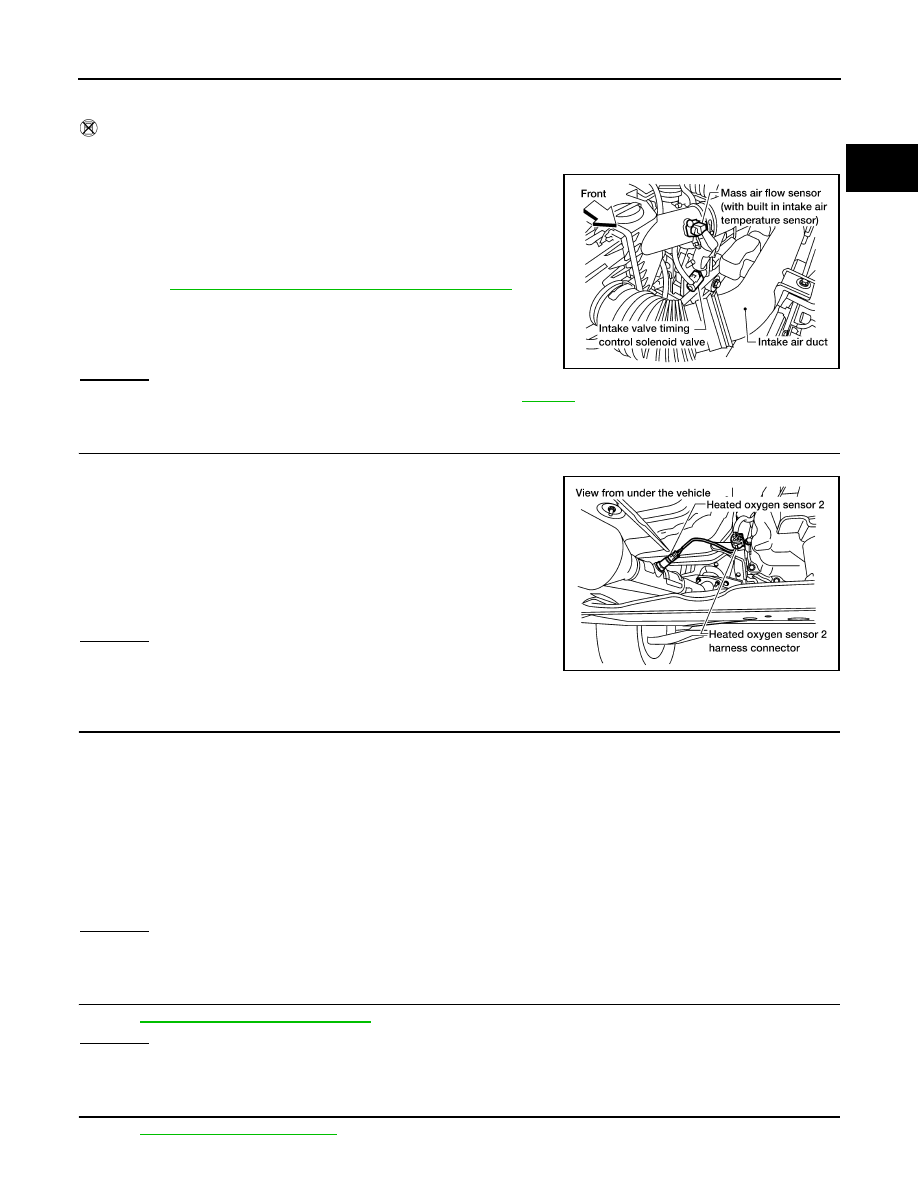
Disconnect heated oxygen sensor 2 harness connector.

3.

Disconnect ECM harness connector.

4.

Check harness continuity between ECM terminal 78 and HO2S2
terminal 4.
Refer to Wiring Diagram.

5.

Also check harness for short to ground and short to power.

OK or NG

OK

>> GO TO 4.

NG

>> Repair open circuit, short to ground or short to power in

harness or connectors.

4.

CHECK HO2S2 INPUT SIGNAL CIRCUIT FOR OPEN AND SHORT

1.

Check harness continuity between ECM terminal 74 and HO2S2 terminal 1.
Refer to Wiring Diagram.

2.

Check harness continuity between ECM terminal 74 or HO2S2 terminal 1 and ground.
Refer to Wiring Diagram.

3.

Also check harness for short to power.

OK or NG

OK

>> GO TO 5.

NG

>> Repair open circuit, short to ground or short to power in harness or connectors.

5.

CHECK HEATED OXYGEN SENSOR 2

Refer to 

EC-156, "Component Inspection"

.

OK or NG

OK

>> GO TO 6.

NG

>> Replace heated oxygen sensor 2.

6.

CHECK INTERMITTENT INCIDENT

Refer to 

GI-46, "Intermittent Incident"

.

BBIA0622E

Continuity should exist.

BBIA0613E

Continuity should exist.

Continuity should not exist.

EC-156

< COMPONENT DIAGNOSIS >

[QR25DE]

P0137 HO2S2

>> INSPECTION END

Component Inspection

INFOID:0000000005273148

HEATED OXYGEN SENSOR 2

 With CONSULT-III

1.

Turn ignition switch ON and select “DATA MONITOR” mode with CONSULT-III.

2.

Start engine and warm it up to the normal operating temperature.

3.

Turn ignition switch OFF and wait at least 10 seconds.

4.

Start engine and keep the engine speed between 3,500 and 4,000 rpm for at least 1 minute under no load.

5.

Let engine idle for 1 minute.

6.

Select “FUEL INJECTION” in “ACTIVE TEST” mode, and select “HO2S2 (B1)” as the monitor item with
CONSULT-III.

7.

Check “HO2S2 (B1)” at idle speed when adjusting “FUEL INJECTION” to 

±

25%.

“HO2S2 (B1)” should be above 0.73V at least once when the “FUEL INJECTION” is +25%.
“HO2S2 (B1)” should be below 0.18V at least once when the “FUEL INJECTION” is 

25%.

CAUTION:

• Discard any heated oxygen sensor which has been dropped from a height of more than 0.5 m

(19.7 in) onto a hard surface such as a concrete floor; use a new one.

• Before installing new oxygen sensor, clean exhaust system threads using Oxygen Sensor

Thread Cleaner [commercial service tool (J-43897-18 or J-43897-12)] and approved anti-seize
lubricant (commercial service tool).

 Without CONSULT-III

1.

Start engine and warm it up to the normal operating temperature.

2.

Turn ignition switch OFF and wait at least 10 seconds.

3.

Start engine and keep the engine speed between 3,500 and 4,000 rpm for at least 1 minute under no load.

4.

Let engine idle for 1 minute.

5.

Set voltmeter probes between ECM terminal 74 (HO2S2 signal) and ground.

6.

Check the voltage when revving up to 4,000 rpm under no load
at least 10 times.
(Depress and release accelerator pedal as soon as possible.)
The voltage should be above 0.73V and below 0.18V at least
once during this procedure.
If the voltage can be confirmed at step 6, step 7 is not nec-
essary.

7.

Keep vehicle at idling for 10 minutes, then check voltage. Or
check the voltage when coasting from 80 km/h (50 MPH) in D
position with OD “OFF”(A/T), 4th gear position (M/T).
The voltage should be above 0.73V and below 0.18V at least
once during this procedure.

8.

If NG, replace heated oxygen sensor 2.

CAUTION:

• Discard any heated oxygen sensor which has been dropped from a height of more than 0.5 m

(19.7 in) onto a hard surface such as a concrete floor; use a new one.

PBIB1920E

PBIB1197E

P0137 HO2S2

EC-157

< COMPONENT DIAGNOSIS >

[QR25DE]

C

D

E

F

G

H

I

J

K

L

M

A

EC

N

P

O

• Before installing new oxygen sensor, clean exhaust system threads using Oxygen Sensor

Thread Cleaner [commercial service tool (J-43897-18 or J-43897-12)] and approved anti-seize
lubricant (commercial service tool).

EC-158

< COMPONENT DIAGNOSIS >

[QR25DE]

P0138 HO2S2

P0138 HO2S2

Component Description

INFOID:0000000005273149

The heated oxygen sensor 2, after three way catalyst (manifold),
monitors the oxygen level in the exhaust gas.
Even if switching characteristics of the A/F sensor 1 are shifted, the
air-fuel ratio is controlled to stoichiometric, by the signal from the
heated oxygen sensor 2.
This sensor is made of ceramic zirconia. The zirconia generates volt-
age from approximately 1V in richer conditions to 0V in leaner condi-
tions.
Under normal conditions the heated oxygen sensor 2 is not used for
engine control operation.

On Board Diagnosis Logic

INFOID:0000000005273150

The heated oxygen sensor 2 has a much longer switching time between rich and lean than the air fuel ratio (A/
F) sensor 1. The oxygen storage capacity of the three way catalyst (manifold) causes the longer switching
time.

MALFUNCTION A

To judge the malfunctions of heated oxygen sensor 2, ECM monitors
whether the voltage is unusually high during various driving condi-
tions such as fuel cut.

MALFUNCTION B

To judge the malfunctions of heated oxygen sensor 2, ECM monitors
whether the minimum voltage of sensor is sufficiently low during var-
ious driving conditions such as fuel cut.

SEF327R

PBIB1848E

PBIB2376E

DTC No.

Trouble diagnosis name

DTC detecting condition

Possible cause

P0138
0138

Heated oxygen sensor 2 
circuit high voltage

A)

An excessively high voltage from the sensor 
is sent to ECM.

• Harness or connectors

(The sensor circuit is open or shorted)

• Heated oxygen sensor 2

B)

The minimum voltage from the sensor is not 
reached to the specified voltage.

• Harness or connectors

(The sensor circuit is open or shorted)

• Heated oxygen sensor 2
• Fuel pressure
• Fuel injector


Content   ..  364  365  366  367   ..