Nissan Frontier D40. Manual - part 360
P0125 ECT SENSOR
EC-131
< COMPONENT DIAGNOSIS >
[QR25DE]
C
D
E
F
G
H
I
J
K
L
M
A
EC
N
P
O
If it is below 10
°
C (50
°
F), go to following step.
4.
Start engine and run it for 65 minutes at idle speed.
If “COOLAN TEMP/S” increases to more than 10
°
C (50
°
F) within 65 minutes, stop engine because
the test result will be OK.
5.
Check 1st trip DTC.
6.
If 1st trip DTC is detected, go to
WITH GST
Follow the procedure WITH CONSULT-III above.
Diagnosis Procedure
INFOID:0000000005273115
1.
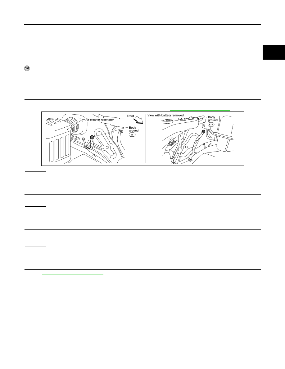
CHECK GROUND CONNECTIONS
1.
Turn ignition switch OFF.
2.
Loosen and retighten two ground screws on the body. Refer to
OK or NG
OK
>> GO TO 2.
NG
>> Repair or replace ground connections.
2.
CHECK ENGINE COOLANT TEMPERATURE SENSOR
EC-131, "Component Inspection"
OK or NG
OK
>> GO TO 3.
NG
>> Replace engine coolant temperature sensor.
3.
CHECK THERMOSTAT OPERATION
When the engine is cold [lower than 70
°
C (158
°
F)] condition, grasp lower radiator hose and confirm the engine
coolant does not flow.
OK or NG
OK
>> GO TO 4.
NG
>> Repair or replace thermostat. Refer to
CO-22, "Removal and Installation Thermostat"
.
4.
CHECK INTERMITTENT INCIDENT
GI-46, "Intermittent Incident"
.
>> INSPECTION END
Component Inspection
INFOID:0000000005273116
ENGINE COOLANT TEMPERATURE SENSOR
BBIA0614E