Nissan Frontier D40. Manual - part 358


  Index      Nissan     Nissan Frontier D40 (2010 year) - Service and Repair Manual


Search            


Content   ..  356  357  358  359   ..


Nissan Frontier D40. Manual - part 358


P0117, P0118 ECT SENSOR

EC-123

< COMPONENT DIAGNOSIS >

[QR25DE]

C

D

E

F

G

H

I

J

K

L

M

A

EC

N

P

O

P0117, P0118 ECT SENSOR

Component Description

INFOID:0000000005273102

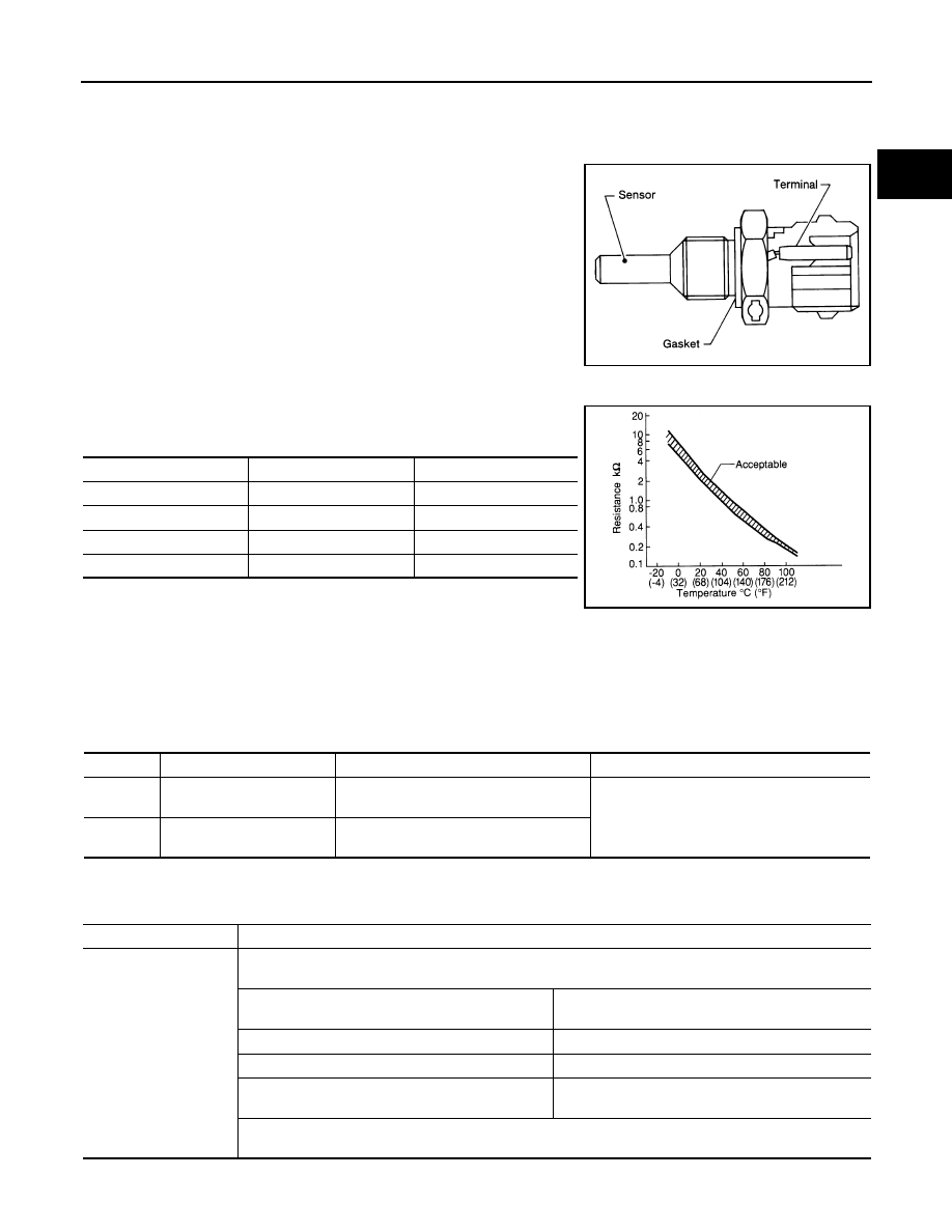
The engine coolant temperature sensor is used to detect the engine
coolant temperature. The sensor modifies a voltage signal from the
ECM. The modified signal returns to the ECM as the engine coolant
temperature input. The sensor uses a thermistor which is sensitive to
the change in temperature. The electrical resistance of the ther-
mistor decreases as temperature increases.

<Reference data>

*: This data is reference value and is measured between ECM terminal 73 (Engine
coolant temperature sensor) and ground.

CAUTION:

Never use ECM ground terminals when measuring input/output voltage. Doing so may result in dam-
age to the ECM's transistor. Use a ground other than ECM terminals, such as the ground.

On Board Diagnosis Logic

INFOID:0000000005273103

These self-diagnoses have the one trip detection logic.

FAIL-SAFE MODE

When this malfunction is detected, the ECM enters fail-safe mode and the MIL lights up.

SEF594K

Engine coolant [

°

C (

°

F)]

Voltage*

(V)

Resistance

(k

)

10 (14)

4.4

7.0 - 11.4

20 (68)

3.5

2.1 - 2.9

50 (122)

2.2

0.68 - 1.00

90 (194)

0.9

0.236 - 0.260

SEF012P

DTC No.

Trouble Diagnosis Name

DTC Detecting Condition

Possible Cause

P0117
0117

Engine coolant temperature 
sensor circuit low input

An excessively low voltage from the sen-
sor is sent to ECM.

• Harness or connectors

(The sensor circuit is open or shorted.)

• Engine coolant temperature sensor 

P0118
0118

Engine coolant temperature 
sensor circuit high input

An excessively high voltage from the sen-
sor is sent to ECM.

Detected items

Engine operating condition in fail-safe mode

Engine coolant temper-

ature sensor circuit

Engine coolant temperature will be determined by ECM based on the following condition.
CONSULT-III displays the engine coolant temperature decided by ECM.

Condition

Engine coolant temperature decided 

(CONSULT-III display)

Just as ignition switch is turned ON or START

40

°

C (104

°

F)

Approx. 4 minutes or more after engine starting.

80

°

C (176

°

F)

Except as shown above

40 - 80

°

C (104 - 176

°

F)

(Depends on the time)

When the fail-safe system for engine coolant temperature sensor is activated, the cooling fan operates while 
engine is running.

EC-124

< COMPONENT DIAGNOSIS >

[QR25DE]

P0117, P0118 ECT SENSOR

DTC Confirmation Procedure

INFOID:0000000005273104

NOTE:
If DTC Confirmation Procedure has been previously conducted, always turn ignition switch OFF and wait at
least 10 seconds before conducting the next test.

 WITH CONSULT-III

1.

Turn ignition switch ON and wait at least 5 seconds.

2.

Check DTC.

3.

If DTC is detected, go to 

EC-124, "Diagnosis Procedure"

.

 WITH GST

Follow the procedure “WITH CONSULT-III” above.

Diagnosis Procedure

INFOID:0000000005273105

1.

CHECK GROUND CONNECTIONS

1.

Turn ignition switch OFF.

2.

Loosen and retighten two ground screws on the body. Refer to 

EC-90, "Ground Inspection"

.

OK or NG

OK

>> GO TO 2.

NG

>> Repair or replace ground connections.

2.

CHECK ECT SENSOR POWER SUPPLY CIRCUIT

1.

Disconnect engine coolant temperature (ECT) sensor harness
connector.

2.

Turn ignition switch ON.

3.

Check voltage between ECT sensor terminal 1 and ground with
CONSULT-III or tester.

OK or NG

OK

>> GO TO 3.

NG

>> Repair open circuit, short to ground or short to power in

harness or connectors.

3.

CHECK ECT SENSOR GROUND CIRCUIT FOR OPEN AND SHORT

BBIA0614E

BBIA0615E

Voltage: Approximately 5 V

PBIB0080E

P0117, P0118 ECT SENSOR

EC-125

< COMPONENT DIAGNOSIS >

[QR25DE]

C

D

E

F

G

H

I

J

K

L

M

A

EC

N

P

O

1.

Turn ignition switch OFF.

2.

Disconnect ECM harness connector.

3.

Check harness continuity between ECT sensor terminal 2 and ECM terminal 67.
Refer to Wiring Diagram.

4.

Also check harness for short to ground and short to power.

OK or NG

OK

>> GO TO 4.

NG

>> Repair open circuit, short to ground or short to power in harness or connectors.

4.

CHECK ENGINE COOLANT TEMPERATURE SENSOR

Refer to 

EC-125, "Component Inspection"

.

OK or NG

OK

>> GO TO 5.

NG

>> Replace engine coolant temperature sensor.

5.

CHECK INTERMITTENT INCIDENT

Refer to 

GI-46, "Intermittent Incident"

.

>> INSPECTION END

Component Inspection

INFOID:0000000005273106

ENGINE COOLANT TEMPERATURE SENSOR

1.

Check resistance between engine coolant temperature sensor
terminals 1 and 2 as shown in the figure.

<Reference data>

2.

If NG, replace engine coolant temperature sensor.

Continuity should exist.

PBIB2005E

Engine coolant temperature [

°

C (

°

F)]

Resistance

(k

)

20 (68)

 2.1 - 2.9

50 (122)

0.68 - 1.00

90 (194)

0.236 - 0.260

SEF012P

EC-126

< COMPONENT DIAGNOSIS >

[QR25DE]

P0122, P0123 TP SENSOR

P0122, P0123 TP SENSOR

Component Description

INFOID:0000000005273107

Electric throttle control actuator consists of throttle control motor,
throttle position sensor, etc. The throttle position sensor responds to
the throttle valve movement. 
The throttle position sensor has two sensors. These sensors are a
kind of potentiometer which transform the throttle valve position into
output voltage, and emit the voltage signal to the ECM. The ECM
judges the current opening angle of the throttle valve from these sig-
nals and controls the throttle valve opening angle in response to
driving conditions via the throttle control motor.

On Board Diagnosis Logic

INFOID:0000000005273108

These self-diagnoses have the one trip detection logic.

FAIL-SAFE MODE

When the malfunction is detected, ECM enters fail-safe mode and the MIL lights up.

DTC Confirmation Procedure

INFOID:0000000005273109

NOTE:
If DTC Confirmation Procedure has been previously conducted, always turn ignition switch OFF and wait at
least 10 seconds before conducting the next test.
TESTING CONDITION:
Before performing the following procedure, confirm that battery voltage is more than 10V at idle.

 WITH CONSULT-III

1.

Start engine and let it idle for 1 second.

2.

Check DTC.

3.

If DTC is detected, go to 

EC-126, "Diagnosis Procedure"

.

 WITH GST

Follow the procedure “WITH CONSULT-III” above.

Diagnosis Procedure

INFOID:0000000005273110

1.

CHECK GROUND CONNECTIONS

1.

Turn ignition switch OFF.

PBIB0145E

DTC No.

Trouble diagnosis name

DTC detecting condition

Possible cause

P0122
0122

Throttle position sensor 
2 circuit low input

An excessively low voltage from the TP 
sensor 2 is sent to ECM.

• Harness or connectors

(The TP sensor 2 circuit is open or shorted.)
(APP sensor 2 circuit is shorted.)

• Electric throttle control actuator

(TP sensor 2)

• Accelerator pedal position sensor

(APP sensor 2)

P0123
0123

Throttle position sensor 
2 circuit high input

An excessively high voltage from the TP 
sensor 2 is sent to ECM.

Engine operation condition in fail-safe mode

The ECM controls the electric throttle control actuator in regulating the throttle opening in order for the idle position to be within +10 
degrees.
The ECM regulates the opening speed of the throttle valve to be slower than the normal condition.
So, the acceleration will be poor. 


Content   ..  356  357  358  359   ..