Nissan Frontier D40. Manual - part 356
P0102, P0103 MAF SENSOR
EC-115
< COMPONENT DIAGNOSIS >
[QR25DE]
C
D
E
F
G
H
I
J
K
L
M
A
EC
N
P
O
With CONSULT-III
1.
Reconnect all harness connectors disconnected.
2.
Start engine and warm it up to normal operating temperature.
3.
Connect CONSULT-III and select “DATA MONITOR” mode.
4.
Select “MAS A/F SE-B1” and check indication under the following conditions.
*: Check for linear voltage rise in response to engine being increased to about 4,000 rpm.
5.
If the voltage is out of specification, proceed the following.
a.
Check for the cause of uneven air flow through mass air flow sensor. Refer to following.
• Crushed air ducts
• Malfunctioning seal of air cleaner element
• Uneven dirt of air cleaner element
• Improper specification of intake air system parts
b.
If NG, repair or replace malfunctioning part and perform step 2 to 4 again.
If OK, go to next step.
6.
Turn ignition switch OFF.
7.
Disconnect mass air flow sensor harness connector and reconnect it again.
8.
Perform step 2 to 4 again.
9.
If NG, clean or replace mass air flow sensor.
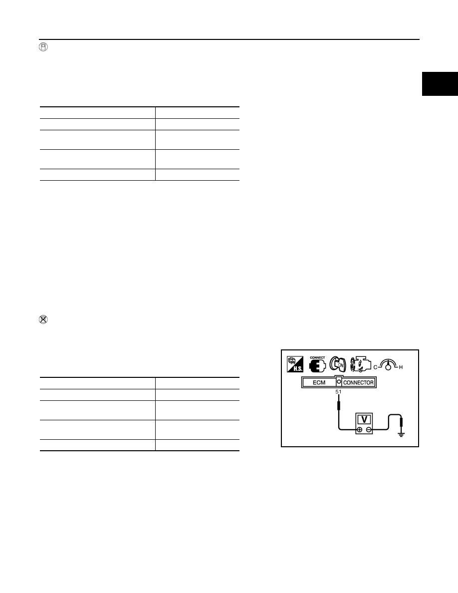
Without CONSULT-III
1.
Reconnect all harness connectors disconnected.
2.
Start engine and warm it up to normal operating temperature.
3.
Check voltage between ECM terminal 51 (Mass air flow sensor
signal) and ground.
*: Check for linear voltage rise in response to engine being increased to about 4,000 rpm.
4.
If the voltage is out of specification, proceed the following.
a.
Check for the cause of uneven air flow through mass air flow sensor. Refer to following.
• Crushed air ducts
• Malfunctioning seal of air cleaner element
• Uneven dirt of air cleaner element
• Improper specification of intake air system parts
b.
If NG, repair or replace malfunctioning part and perform step 2 and 3 again.
If OK, go to next step.
5.
Turn ignition switch OFF.
6.
Disconnect mass air flow sensor harness connector and reconnect it again.
7.
Perform step 2 and 3 again.
Condition
MAS A/F SE-B1 (V)
Ignition switch ON (Engine stopped.)
Approx. 0.4
Idle (Engine is warmed-up to normal
operating temperature.)
0.9 - 1.2
2,500 rpm (Engine is warmed-up to
normal operating temperature.)
1.5 - 1.9
Idle to about 4,000 rpm
0.9 - 1.2 to Approx. 2.4*
Condition
Voltage (V)
Ignition switch ON (Engine stopped.)
Approx 0.4
Idle (Engine is warmed-up to normal
operating temperature.)
0.9 - 1.2
2,500 rpm (Engine is warmed-up to
normal operating temperature.)
1.5 - 1.9
Idle to about 4,000 rpm
0.9 - 1.2 to Approx. 2.4*
PBIB1106E