Nissan Frontier D40. Manual - part 183


  Index      Nissan     Nissan Frontier D40 (2010 year) - Service and Repair Manual


Search            


Content   ..  181  182  183  184   ..


Nissan Frontier D40. Manual - part 183


CL-18

< REMOVAL AND INSTALLATION >

CLUTCH RELEASE MECHANISM

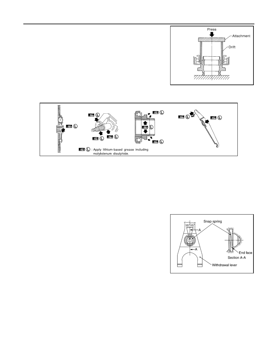
• Install the release bearing to release bearing sleeve using suitable

tool, as shown.

• Clean old grease and abrasive materials off the grease application areas.
• Apply grease to the specified points as shown.

• Apply approximately 1 mm (0.04 in) thick coat of clutch sleeve grease to withdrawal lever and holder spring

frictional surfaces.

• Apply a coat of clutch sleeve grease to ball pin contact surface of the withdrawal lever and inner slots of the

release bearing. The grease surface should be level with the surrounding area.

• Apply a thin coat of clutch sleeve grease to the release bearing frictional surface. After grease application,

Install release bearing. Wipe off excess grease forced out during bearing installation.

CAUTION:

• Before installing the manual transaxle to the vehicle, check that each sliding surface slides smoothly

by operating withdrawal lever.

• Be careful not to bring any grease into contact with the clutch disc facing, pressure plate surface, or

flywheel surface.

• When assembling, make sure that both ends of the snap

spring touch the end face of the withdrawal lever.

• Be careful with the orientation of the installation.

6M/T : Inspection

INFOID:0000000005276149

INSPECTION AFTER REMOVAL

WCL025

SCIA1362E

SCIA6903E

CLUTCH RELEASE MECHANISM

CL-19

< REMOVAL AND INSTALLATION >

C

E

F

G

H

I

J

K

L

M

A

B

CL

N

O

P

• Replace the release bearing if it is seized, damaged, faulty in rota-

tion direction, or has poor aligning function.

• Replace the withdrawal lever if its contact surface is worn abnor-

mally.

• Replace the dust seal if it is deformed or cracked.

SCL733

CL-20

< REMOVAL AND INSTALLATION >

CLUTCH DISC, CLUTCH COVER

CLUTCH DISC, CLUTCH COVER

5M/T

5M/T : Exploded View

INFOID:0000000005276150

5M/T : Removal and Installation

INFOID:0000000005276151

CAUTION:

• Do not clean the clutch disc with solvent.
• When installing, do not get grease from the main drive shaft onto the clutch disc friction surface. 

REMOVAL

1.

Remove the manual transmission from the vehicle. Refer to 

TM-19, "Removal and Installation from Vehi-

cle"

.

2.

Remove the clutch cover bolts using power tool. Remove the clutch cover and clutch disc.

INSTALLATION

1.

Apply recommended grease to clutch disc and main drive shaft spline.

CAUTION:

Do not allow grease to contaminate the clutch facing.

1.

Flywheel

2.

Clutch disc

3.

Clutch cover

WCIA0522E

CLUTCH DISC, CLUTCH COVER

CL-21

< REMOVAL AND INSTALLATION >

C

E

F

G

H

I

J

K

L

M

A

B

CL

N

O

P

2.

Install clutch disc and clutch cover. Pre-tighten the bolts and
install Tool. Then tighten the clutch cover bolts evenly in two
steps to the specified torque in the order shown. Refer to 

CL-20,

"5M/T : Exploded View"

.

3.

Install the manual transmission. Refer to 

TM-19, "Removal and Installation from Vehicle"

.

5M/T : Inspection after Removal

INFOID:0000000005276152

INSPECTION  AFTER REMOVAL

Clutch Disc

• Check the wear of the clutch disc facing.

• Check the runout and backlash of the clutch disc. If the measure-

ment exceeds the specification, replace the clutch disc.

Clutch Cover

• Check clutch cover thrust ring for wear or damage. If wear or damage is found, replace clutch cover assem-

bly.
NOTE:
• Worn thrust ring will generate a beating noise when tapped at the rivet with a hammer.

Tool number

: ST20630000 (J-26366)

WCIA0504E

Clutch disc facing 
wear

: Refer to 

CL-25, "Clutch Disc"

.

SCL229

Runout and backlash

: Refer to 

CL-25, "Clutch Disc"

.

SCL221


Content   ..  181  182  183  184   ..