Nissan Frontier D40. Manual - part 1063


  Index      Nissan     Nissan Frontier D40 (2010 year) - Service and Repair Manual


Search            


Content   ..  1061  1062  1063  1064   ..


Nissan Frontier D40. Manual - part 1063


TM-150

< FUNCTION DIAGNOSIS >

[5AT: RE5R05A]

ON BOARD DIAGNOSTIC (OBD) SYSTEM

longer stored. Remember, only one set of freeze frame data can be stored in the ECM. The ECM has the fol-
lowing priorities to update the data.

Both 1st trip freeze frame data and freeze frame data (along with the DTC) are cleared when the ECM mem-
ory is erased.

HOW TO ERASE DTC

The diagnostic trouble code can be erased by CONSULT-III, GST or ECM DIAGNOSTIC TEST MODE as
described following.
• If the battery cable is disconnected, the diagnostic trouble code will be lost within 24 hours. 
• When you erase the DTC, using CONSULT-III or GST is easier and quicker than switching the mode

selector on the ECM.

The following emission-related diagnostic information is cleared from the ECM memory when erasing DTC
related to OBD-II. For details, refer to 

EC-47, "Emission-related Diagnostic Information"

 (QR25DE) or 

EC-501,

"Emission-related Diagnostic Information"

 (VQ40DE).

• Diagnostic trouble codes (DTC)
• 1st trip diagnostic trouble codes (1st trip DTC)
• Freeze frame data
• 1st trip freeze frame data
• System readiness test (SRT) codes
• Test values

 HOW TO ERASE DTC (WITH CONSULT-III)

1.

The emission related diagnostic information in the TCM and ECM can be erased by selecting “ALL Erase”
in the “Description” of “FINAL CHECK” mode with CONSULT-III.

 HOW TO ERASE DTC (WITH GST)

1.

If the ignition switch stays “ON” after repair work, be sure to turn ignition switch “OFF” once. Wait at least
10 seconds and then turn it “ON” (engine stopped) again.

2.

Select Mode 4 with the Generic Scan Tool (GST). For details refer to 

EC-76, "Generic Scan Tool (GST)

Function"

 (QR25DE) or 

EC-536, "Generic Scan Tool (GST) Function"

 (VQ40DE).

 HOW TO ERASE DTC (NO TOOLS)

1.

Disconnect battery for 24 hours.

2.

Reconnect battery.

Malfunction Indicator Lamp (MIL)

INFOID:0000000005273995

DESCRIPTION 

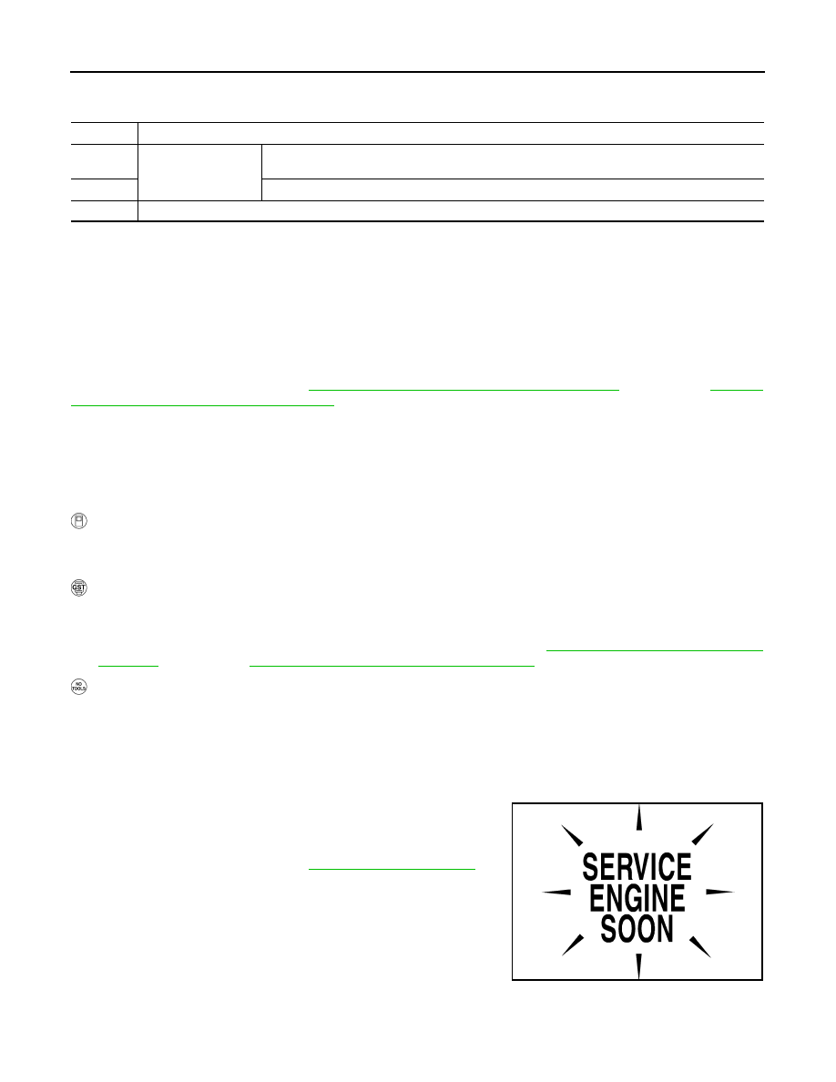
The MIL is located on the instrument panel.

1.

The MIL will light up when the ignition switch is turned “ON” with-
out the engine running. This is a bulb check.

• If the MIL does not light up, refer to 

MWI-41, "Wiring Diagram"

.

2.

When the engine is started, the MIL should go off.
If the MIL remains on, the on board diagnostic system has
detected an engine system malfunction.

Priority

Items

1

Freeze frame data

Misfire — DTC: P0300 - P0306
Fuel Injection System Function — DTC: P0171, P0172, P0174, P0175

2

Except the above items (Includes A/T related items)

3

1st trip freeze frame data

SEF217U

DIAGNOSIS SYSTEM (TCM)

TM-151

< FUNCTION DIAGNOSIS >

[5AT: RE5R05A]

C

E

F

G

H

I

J

K

L

M

A

B

TM

N

O

P

DIAGNOSIS SYSTEM (TCM)

CONSULT-III Function (TRANSMISSION)

INFOID:0000000005273996

FUNCTION

SELF-DIAGNOSTIC RESULT MODE

Display Items List

X: Applicable, —: Not applicable

TCM diagnostic mode

Description

Work Support

This mode enables a technician to adjust some devices faster and more accurately.

Self-Diagnostic Results

Retrieve DTC from ECU and display diagnostic items.

Data Monitor

Monitor the input/output signal of the control unit in real time.

CAN Diagnosis Support Mon-
itor

It monitors the status of CAN communication.

DTC & SRT Confirmation

The status of system monitoring tests and the self-diagnosis status/result can be confirmed.

ECU Identification

Display the ECU identification number (part number etc.) of the selected system.

 Items (CONSULT-III 

screen terms)

Malfunction is detected when...

TCM self-diag-

nosis

OBD-II (DTC)

Reference 

page

“TRANSMIS-

SION” with   

CONSULT-III

MIL indicator 
lamp*1, “EN-

GINE” with 

CONSULT-III or 

GST

CAN COMM CIRCUIT

• When TCM is not transmitting or receiving CAN com-

munication signal for 2 seconds or more.

U1000

U1000

TM-159

STARTER RELAY

• If this signal is ON other than in “P” or “N” position, this 

is judged to be a malfunction.
(And if it is OFF in “P” or “N” position, this too is judged 
to be a malfunction.)

P0615

TM-160

TRANSMISSION CONT

• TCM is malfunctioning.

P0700

P0700

TM-162

T/M RANGE SWITCH A

• Transmission range switch 1-4 signals input with im-

possible pattern

• “P” position is detected from “N” position without any 

other position being detected in between.

P0705

P0705

TM-163

INPUT SPEED SEN-
SOR A

• TCM does not receive the proper voltage signal from 

the sensor.

• TCM detects an irregularity only at position of 4GR for 

input speed sensor 2.

P0717

P0717

TM-165

OUTPUT SPEED SEN-
SOR

• Signal from output speed sensor not input due to cut 

line or the like

• Unexpected signal input during running
• After ignition switch is turned ON, unexpected signal 

input from vehicle speed signal before the vehicle 
starts moving

P0720

P0720

TM-167

ENGINE SPEED

• TCM does not receive the CAN communication signal 

from the ECM.

P0725

TM-170

1GR INCORRECT RA-
TIO

• A/T cannot shift to 1GR

P0731

P0731

TM-173

2GR INCORRECT RA-
TIO

• A/T cannot shift to 2GR

P0732

P0732

TM-175

3GR INCORRECT RA-
TIO

• A/T cannot shift to 3GR

P0733

P0733

TM-177

TM-152

< FUNCTION DIAGNOSIS >

[5AT: RE5R05A]

DIAGNOSIS SYSTEM (TCM)

4GR INCORRECT RA-
TIO

• A/T cannot shift to 4GR

P0734

P0734

TM-179

5GR INCORRECT RA-
TIO

• A/T cannot shift to 5GR

P0735

P0735

TM-181

TORQUE CONVERTER

• Normal voltage not applied to solenoid due to cut line, 

short, or the like

P0740

P0740

TM-182

TORQUE CONVERTER

• A/T cannot perform lock-up even if electrical circuit is 

good.

• TCM detects as irregular by comparing difference val-

ue with slip rotation.

P0744

P0744*2

TM-184

PC SOLENOID A

• Normal voltage not applied to solenoid due to cut line, 

short, or the like

• TCM detects as irregular by comparing target value 

with monitor value.

P0745

P0745

TM-186

TP SENSOR

• TCM does not receive the proper accelerator pedal 

position signals (input by CAN communication) from 
ECM.

P1705

TM-188

TRANS FLUID TEMP 
SEN

•  During running, the ATF temperature sensor signal 

voltage is excessively high or low

P1710

P0710

TM-190

VEHICLE SPEED SIG-
NAL

• Signal (CAN communication) from vehicle speed sig-

nal not input due to cut line or the like

• Unexpected signal input during running

P1721

TM-192

INTERLOCK

• Except during shift change, the gear position and ATF 

pressure switch states are monitored and compara-
tive judgment made.

P1730

P1730

TM-194

1ST E/BRAKING

• Each ATF pressure switch and solenoid current is 

monitored and if a pattern is detected having engine 
braking 1GR other than in the “1” position, a malfunc-
tion is detected.

P1731

TM-196

INPUT CLUTCH SOL

• Normal voltage not applied to solenoid due to func-

tional malfunction, cut line, short, or the like

• TCM detects as irregular by comparing target value 

with monitor value.

P1752

P1752

TM-198

FR BRAKE SOLENOID

• Normal voltage not applied to solenoid due to func-

tional malfunction, cut line, short, or the like

• TCM detects as irregular by comparing target value 

with monitor value.

P1757

P1757

TM-200

DRCT CLUTCH SOL

• Normal voltage not applied to solenoid due to cut line, 

short, or the like

• TCM detects as irregular by comparing target value 

with monitor value.

P1762

P1762

TM-202

HLR CLUTCH SOLE-
NOID

• Normal voltage not applied to solenoid due to func-

tional malfunction, cut line, short, or the like

• TCM detects as irregular by comparing target value 

with monitor value.

P1767

P1767

TM-204

L C BRAKE SOLENOID

• Normal voltage not applied to solenoid due to func-

tional malfunction, cut line, short, or the like

P1772

P1772

TM-206

 Items (CONSULT-III 

screen terms)

Malfunction is detected when...

TCM self-diag-

nosis

OBD-II (DTC)

Reference 

page

“TRANSMIS-

SION” with   

CONSULT-III

MIL indicator 
lamp*1, “EN-

GINE” with 

CONSULT-III or 

GST

DIAGNOSIS SYSTEM (TCM)

TM-153

< FUNCTION DIAGNOSIS >

[5AT: RE5R05A]

C

E

F

G

H

I

J

K

L

M

A

B

TM

N

O

P

*1: Refer to 

TM-150, "Malfunction Indicator Lamp (MIL)"

.

*2:These malfunctions cannot be displayed MIL if another malfunction is assigned to MIL.

DATA MONITOR MODE

Display Items List

 X: Standard, —: Not applicable, 

: Option

L C BRAKE SOLENOID

• TCM detects an improper voltage drop when it tries to 

operate the solenoid valve.

• Condition of ATF pressure switch 2 is different from 

monitor value, and relation between gear position and 
actual gear ratio is irregular.

P1774

P1774*2

TM-208

NO DTC IS DETECTED 
FURTHER TESTING 
MAY BE REQUIRED

• No NG item has been detected.

X

X

 Items (CONSULT-III 

screen terms)

Malfunction is detected when...

TCM self-diag-

nosis

OBD-II (DTC)

Reference 

page

“TRANSMIS-

SION” with   

CONSULT-III

MIL indicator 
lamp*1, “EN-

GINE” with 

CONSULT-III or 

GST

Monitored item (Unit)

Monitor Item Selection

Remarks

ECU IN-

PUT SIG-

NALS

MAIN SIG-

NALS

SELEC-

TION 

FROM 
MENU

VHCL/S SE·A/T (km/h or mph)

X

X

Output speed sensor

VHCL/S SE·MTR (km/h or mph)

X

ACCELE POSI (0.0/8) 

X

Accelerator pedal position signal

THROTTLE POSI (0.0/8)

X

X

Degree of opening for accelerator recognized by 
the TCM
For fail-safe operation, the specific value used 
for control is displayed.

CLSD THL POS (ON-OFF display)

X

Signal input with CAN communications

W/O THL POS (ON-OFF display)

X

BRAKESW (ON-OFF display)

X

Stop lamp switch

GEAR

X

Gear position recognized by the TCM updated 
after gear-shifting

ENGINE SPEED (rpm) 

X

X

INPUT SPEED (rpm) 

X

X

OUTPUT REV (rpm) 

X

X

GEAR RATIO

X

TC SLIP SPEED (rpm)

X

Difference between engine speed and torque 
converter input shaft speed

F SUN GR REV (rpm) 

F CARR GR REV (rpm)

ATF TEMP SE 1 (V)

X

ATF TEMP 1 (

°

C or 

°

F)

X

ATF TEMP 2 (

°

C or 

°

F)

X


Content   ..  1061  1062  1063  1064   ..