Content .. 1028 1029 1030 1031 ..
Nissan Frontier D40. Manual - part 1030
TM-18
< ON-VEHICLE REPAIR >
[FS5R30A]
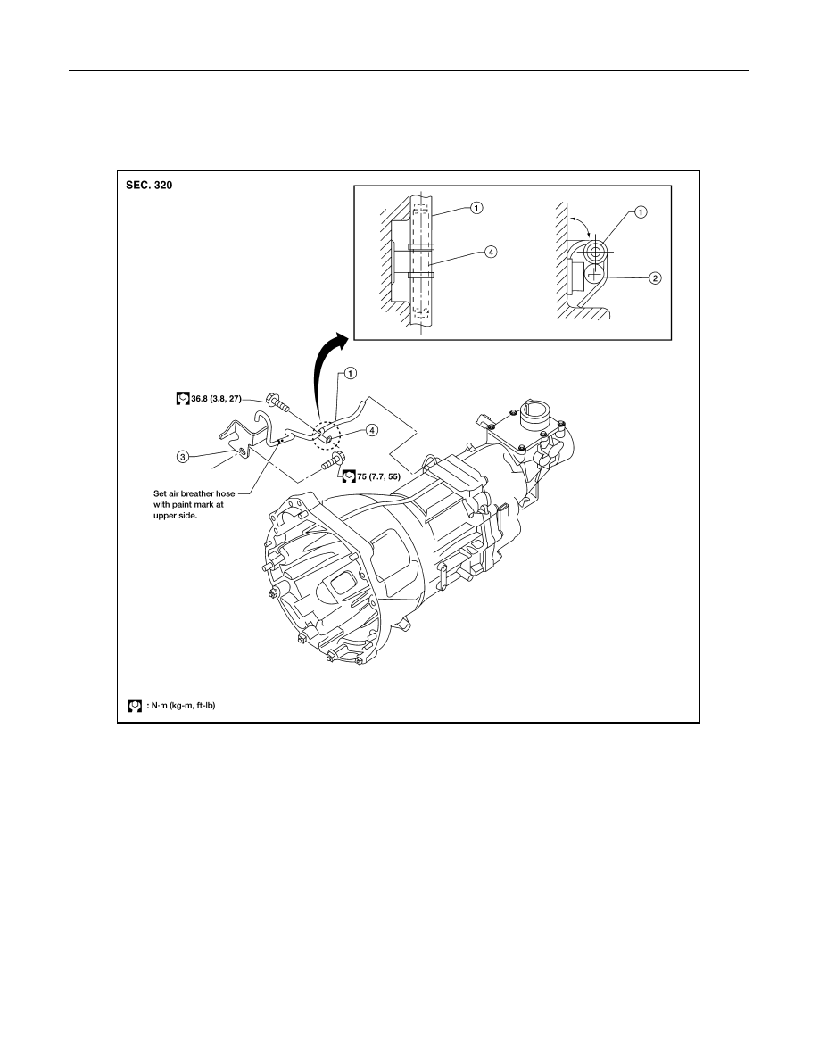
AIR BREATHER HOSE
AIR BREATHER HOSE
Removal and Installation
INFOID:0000000005273940
Refer to the figure below for air breather hose removal and installation information.
CAUTION:
• Make sure there are no pinched or blocked areas on the air breather hose after installation.
• When inserting the air breather hose, be sure to insert it fully until its end reaches the end of the tube
radius.
• Install the air breather hose with the paint mark side up.
• Install the air breather hose and harness to the clip to prevent separation.
• Push the harness so that it contacts with the interlocking bolt.
1.
Air breather hose
2.
Harness
3.
Breather tube
4.
Clip
LCIA0380E