Nissan Frontier D40. Manual - part 1029


  Index      Nissan     Nissan Frontier D40 (2010 year) - Service and Repair Manual


Search            


Content   ..  1027  1028  1029  1030   ..


Nissan Frontier D40. Manual - part 1029


TM-14

< ON-VEHICLE REPAIR >

[FS5R30A]

REAR OIL SEAL

ON-VEHICLE REPAIR

REAR OIL SEAL

Removal and Installation

INFOID:0000000005273937
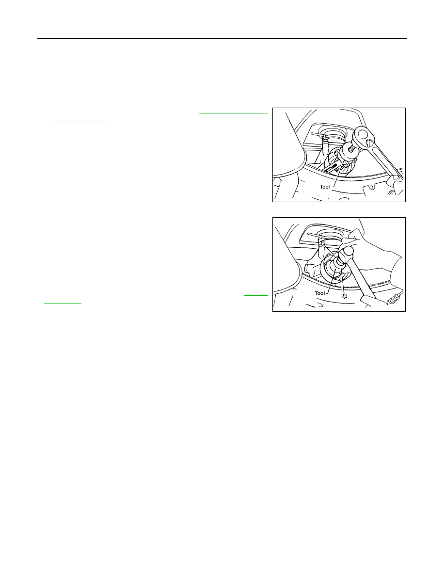
REMOVAL

1.

Remove the rear propeller shaft. Refer to 

DLN-144, "Removal

and Installation"

.

2.

Remove the rear oil seal using Tool.

CAUTION:

Do not reuse rear oil seal.

INSTALLATION

Installation is the reverse order of removal.
• Drive the new oil seal straight until it stops using Tool.

CAUTION:

• Do not reuse rear oil seal.
• Apply multi-purpose grease to oil seal lips before installing.
• Do not incline rear oil seal during installation.

• Check the transmission oil level after installation. Refer to 

TM-13,

"Checking"

.

Tool number

: ST33290001 (J-34286)

WCIA0176E

Tool number

: ST30720000 (J-25405)

WCIA0493E

POSITION SWITCH

TM-15

< ON-VEHICLE REPAIR >

[FS5R30A]

C

E

F

G

H

I

J

K

L

M

A

B

TM

N

O

P

POSITION SWITCH

Checking

INFOID:0000000005273938

BACK-UP LAMP SWITCH

• Check continuity.

PARK/NEUTRAL POSITION SWITCH

• Check continuity.

Gear position

Continuity

Reverse

Yes

Except reverse

No

SMT981D

Gear position

Continuity

Neutral

Yes

Except neutral

No

TM-16

< ON-VEHICLE REPAIR >

[FS5R30A]

SHIFT CONTROL

SHIFT CONTROL

Removal and Installation

INFOID:0000000005273939

COMPONENTS

REMOVAL

1.

Remove the shift knob.

2.

Remove the cup holder finisher and shift bezel. Refer to 

IP-19, "Exploded View"

.

3.

Remove the retaining plate and dust boot covers.

4.

Remove the clip (B) and then separate the boot from the control housing. 

5.

Remove the snap ring. 

6.

Remove the shift lever assembly from the transmission.

INSTALLATION

Installation is the reverse order of removal.

CAUTION:

• Do not reuse the clip and snap ring.

1.

Retaining plate

2.

Dust boot cover (upper)

3.

Dust boot cover (lower)

4.

Shift knob

5.

Shift lever assembly

6.

Clip (A) 

7.

Boot

8.

Clip (B)

9.

Snap ring

AWDIA0626ZZ

SHIFT CONTROL

TM-17

< ON-VEHICLE REPAIR >

[FS5R30A]

C

E

F

G

H

I

J

K

L

M

A

B

TM

N

O

P

• Apply cement to threads of the shift lever assembly.
• When shift lever assembly is shifted to each position, make sure there is no binding or disconnection in

either boot.


Content   ..  1027  1028  1029  1030   ..