Nissan Frontier D40. Manual - part 99


  Index      Nissan     Nissan Frontier D40 (2010 year) - Service and Repair Manual


Search            


Content   ..  97  98  99  100   ..


Nissan Frontier D40. Manual - part 99


BRC-94

< FUNCTION DIAGNOSIS >

[TYPE 2]

EBD

Component Description

INFOID:0000000005549015

10. Rear wheel sensor LH C11

Rear wheel sensor RH C10

11.

Steering angle sensor (behind spiral ca-
ble) M47
(Steering wheel removed for clarity)

12. VDC OFF switch M154

13. Stop lamp switch (with M/T) E38

Stop lamp switch (with A/T) E39
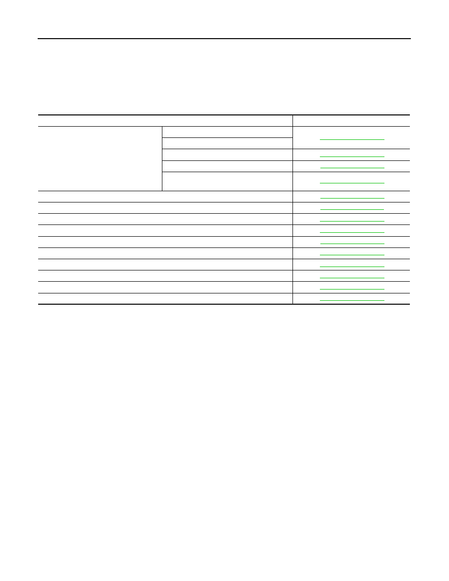
Component parts

Reference

ABS actuator and electric unit (control unit)

Pump

BRC-109, "Description"

Motor

Actuator relay

BRC-126, "Description"

Solenoid valve

BRC-118, "Description"

VDC switch-over valve
(CV1, CV2, SV1, SV2)

BRC-137, "Description"

Wheel sensor

BRC-113, "Description"

Yaw rate/side/decel G sensor

BRC-111, "Description"

Brake fluid level switch

BRC-128, "Description"

Steering angle sensor

BRC-128, "Description"

Stop lamp switch

BRC-116, "Description"

VDC OFF switch

BRC-142, "Description"

ABS warning lamp

BRC-144, "Description"

Brake warning lamp

BRC-145, "Description"

VDC OFF indicator lamp

BRC-146, "Description"

SLIP indicator lamp

BRC-148, "Description"

DIAGNOSIS SYSTEM [ABS ACTUATOR AND ELECTRIC UNIT (CONTROL 

UNIT)]

BRC-95

< FUNCTION DIAGNOSIS >

[TYPE 2]

C

D

E

G

H

I

J

K

L

M

A

B

BRC

N

O

P

DIAGNOSIS SYSTEM [ABS ACTUATOR AND ELECTRIC UNIT (CONTROL
UNIT)]

CONSULT-III Function (ABS)

INFOID:0000000005548239

FUNCTION

CONSULT-III can display each diagnostic item using the diagnostic test modes shown following.

SELF DIAGNOSTIC RESULT MODE

Operation Procedure

1.

Before performing the self-diagnosis, start engine and drive vehicle at 30 km/h (19 MPH) or more for
approximately 1 minute.

How to Erase Self-diagnosis Results

1.

After erasing DTC memory, start engine and drive vehicle at 30 km/h (19 MPH) or more for approximately
1 minute as the final inspection, and make sure that the ABS warning lamp, VDC OFF indicator lamp,
SLIP indicator lamp and brake warning lamp turn OFF.

CAUTION:

If memory cannot be erased, perform applicable diagnosis.
NOTE:
• When the wheel sensor malfunctions, after inspecting the wheel sensor system, the ABS warning lamp,

VDC OFF indicator lamp, SLIP indicator lamp and brake warning lamp will not turn OFF even when the
system is normal unless the vehicle is driving at approximately 30 km/h (19 MPH) or more for approxi-
mately 1 minute.

• Brake warning lamp will turn ON in case of parking brake operation (when switch is ON) or of brake fluid

level switch operation (when brake fluid is insufficient).

• VDC OFF switch should not stay “ON” position.

Display Item List

Refer to 

BRC-163, "DTC No. Index"

.

DATA MONITOR MODE

Display Item List

Diagnostic test mode

Function

Ecu Identification

ABS actuator and electric unit (control unit) part number can be read.

Self Diagnostic Result

Self-diagnostic results can be read and erased quickly.

Data Monitor

Input/Output data in the ABS actuator and electric unit (control unit) can be read.

Active Test

Diagnostic test mode is which CONSULT-III drives some actuators apart from the ABS actuator 
and electric unit (control unit) and also shifts some parameters in a specified range.

Function Test

Other results or histories, etc. that are recorded in ECU are displayed.

Work support

This mode enables a technician to adjust some devices faster and more accurately.

CAN Diag Support Mntr

The results of transmit/receive diagnosis of CAN communication can be read.

Item

(Unit)

Data monitor item selection

Remarks

ECU INPUT 

SIGNALS

MAIN

SIGNALS

SELECTION

FROM MENU

FR LH SENSOR 
 (km/h, mph)

×

×

×

Wheel speed calculated by front LH 
wheel sensor signal is displayed.

FR RH SENSOR 
 (km/h, mph)

×

×

×

Wheel speed calculated by front RH 
wheel sensor signal is displayed.

RR LH SENSOR 
 (km/h, mph)

×

×

×

Wheel speed calculated by rear LH 
wheel sensor signal is displayed.

RR RH SENSOR
 (km/h, mph)

×

×

×

Wheel speed calculated by rear RH 
wheel sensor signal is displayed.

BRC-96

< FUNCTION DIAGNOSIS >

[TYPE 2]

DIAGNOSIS SYSTEM [ABS ACTUATOR AND ELECTRIC UNIT (CONTROL 

UNIT)]

DECEL G-SEN
(G)

×

×

×

Longitudinal acceleration detected 
by decel G-sensor is displayed.

FR RH IN SOL
(ON/OFF)

×

×

Front RH IN ABS solenoid (ON/
OFF) status is displayed.

FR RH OUT SOL
(ON/OFF)

×

×

Front RH OUT ABS solenoid (ON/
OFF) status is displayed.

FR LH IN SOL
(ON/OFF)

×

×

Front LH IN ABS solenoid (ON/
OFF) status is displayed.

FR LH OUT SOL
(ON/OFF)

×

×

Front LH OUT ABS solenoid (ON/
OFF) status is displayed.

RR RH IN SOL
(ON/OFF)

×

×

Rear RH IN ABS solenoid (ON/
OFF) status is displayed.

RR RH OUT SOL
(ON/OFF) 

×

×

Rear RH OUT ABS solenoid (ON/
OFF) status is displayed.

RR LH IN SOL
(ON/OFF)

×

×

Rear LH IN ABS solenoid (ON/OFF) 
status is displayed.

RR LH OUT SOL
(ON/OFF)

×

×

Rear LH OUT ABS solenoid (ON/
OFF) status is displayed.

EBD WARN LAMP
(ON/OFF)

×

Brake warning lamp (ON/OFF) sta-
tus is displayed.

STOP LAMP SW
(ON/OFF)

×

×

×

Stop lamp switch (ON/OFF) status 
is displayed.

MOTOR RELAY
(ON/OFF)

×

×

ABS motor relay signal (ON/OFF) 
status is displayed.

ACTUATOR RLY
(ON/OFF)

×

×

ABS actuator relay signal (ON/OFF) 
status is displayed.

ABS WARN LAMP
(ON/OFF)

×

×

ABS warning lamp (ON/OFF) status 
is displayed.

OFF LAMP
(ON/OFF)

×

×

OFF Lamp (ON/OFF) status is dis-
played.

OFF  SW
(ON/OFF)

×

×

×

VDC OFF switch (ON/OFF) status 
is displayed.

SLIP LAMP
(ON/OFF)

×

×

SLIP indicator lamp (ON/OFF) sta-
tus is displayed.

BATTERY VOLT
(V)

×

×

×

Voltage supplied to ABS actuator 
and electric unit (control unit) is dis-
played.

GEAR
 (1, 2, 3, 4, 5)

×

×

×

Gear position determined by TCM is 
displayed.

SLCT LVR POSI
(P, R, N, D)

×

×

×

Shift position judged by PNP switch 
signal.

ENGINE SPEED
(rpm)

×

×

×

Engine speed judged by CAN com-
munication signal is displayed.

YAW RATE SEN
(d/s)

×

×

×

Yaw rate detected by yaw rate sen-
sor is displayed.

R POSI SIG
(ON/OFF)

×

Shift position judged by PNP switch 
signal.

N POSI SIG
(ON/OFF)

×

Shift position judged by PNP switch 
signal.

P POSI SIG
(ON/OFF)

×

Shift position judged by PNP switch 
signal.

Item

(Unit)

Data monitor item selection

Remarks

ECU INPUT 

SIGNALS

MAIN

SIGNALS

SELECTION

FROM MENU

DIAGNOSIS SYSTEM [ABS ACTUATOR AND ELECTRIC UNIT (CONTROL 

UNIT)]

BRC-97

< FUNCTION DIAGNOSIS >

[TYPE 2]

C

D

E

G

H

I

J

K

L

M

A

B

BRC

N

O

P

×

: Applicable

–: Not applicable

ACTIVE TEST MODE

CV1
(ON/OFF)

×

Front side switch-over solenoid 
valve (cut valve) (ON/OFF) status is 
displayed.

CV2
(ON/OFF)

×

Rear side switch-over solenoid 
valve (cut-valve) (ON/OFF) status is 
displayed.

SV1
(ON/OFF)

×

Front side switch-over solenoid 
valve (suction valve) (ON/OFF) sta-
tus is displayed.

SV2
(ON/OFF)

×

Rear side switch-over solenoid 
valve (suction valve) (ON/OFF) sta-
tus is displayed.

2WD/4WD
(2WD/4WD)

×

It recognizes on software whether it 
is 2WD and whether it is in 4WD 
state.

ACCEL POS SIG
(%)

×

×

Throttle valve open/close status 
judged by CAN communication sig-
nal is displayed.

SIDE G-SENSOR

 (m/s

2

)

×

×

Transverse acceleration detected 
by side G-sensor is displayed. 

STR ANGLE SIG
(deg)

×

×

Steering angle detected by steering 
angle sensor is displayed.

PRESS SENSOR
(bar)

×

×

Brake pressure detected by pres-
sure sensor is displayed.

EBD SIGNAL
(ON/OFF)

×

EBD operation (ON/OFF) status is 
displayed.

ABS SIGNAL
(ON/OFF)

×

ABS operation (ON/OFF) status is 
displayed.

TCS SIGNAL
(ON/OFF)

×

TCS operation (ON/OFF) status is 
displayed.

VDC SIGNAL
(ON/OFF)

×

VDC operation (ON/OFF) status is 
displayed.

EBD FAIL SIG
(ON/OFF)

×

EBD fail signal (ON/OFF) status is 
displayed.

ABS FAIL SIG
(ON/OFF)

×

ABS fail signal (ON/OFF) status is 
displayed.

TCS FAIL SIG
(ON/OFF)

×

TCS fail signal (ON/OFF) status is 
displayed.

VDC FAIL SIG
(ON/OFF)

×

VDC fail signal (ON/OFF) status is 
displayed.

CRANKING SIG
(ON/OFF)

×

The input state of the key SW 
START position signal is displayed.

FLUID LEV SW
(ON/OFF)

×

×

Brake fluid level switch (ON/OFF) 
status is displayed.

DLOCK SW
(ON/OFF)

×

Condition of differential lock mode 
switch (ON/OFF) is displayed.

DLOCK CHG SW
(ON/OFF)

×

Condition of differential lock position 
switch (ON/OFF) is displayed.

Item

(Unit)

Data monitor item selection

Remarks

ECU INPUT 

SIGNALS

MAIN

SIGNALS

SELECTION

FROM MENU


Content   ..  97  98  99  100   ..