Nissan Frontier D40. Manual - part 100


  Index      Nissan     Nissan Frontier D40 (2010 year) - Service and Repair Manual


Search            


Content   ..  98  99  100  101   ..


Nissan Frontier D40. Manual - part 100


BRC-98

< FUNCTION DIAGNOSIS >

[TYPE 2]

DIAGNOSIS SYSTEM [ABS ACTUATOR AND ELECTRIC UNIT (CONTROL 

UNIT)]

CAUTION:

• Do not perform active test while driving vehicle.
• Make sure to completely bleed air from brake system.
• The active test cannot be performed with the ABS warning lamp, VDC OFF indicator lamp, SLIP indi-

cator lamp or brake warning lamp on.

• ABS warning lamp, VDC OFF indicator lamp, SLIP indicator lamp and brake warning lamp are on

during active test.

NOTE:
• When active test is performed while depressing the pedal, the pedal depression amount will change. This is

normal. (Only solenoid valve and ABS motor.)

• “TEST IS STOPPED” is displayed 10 seconds after operation start.
• After “TEST IS STOPPED” is displayed, to perform test again, touch BACK.
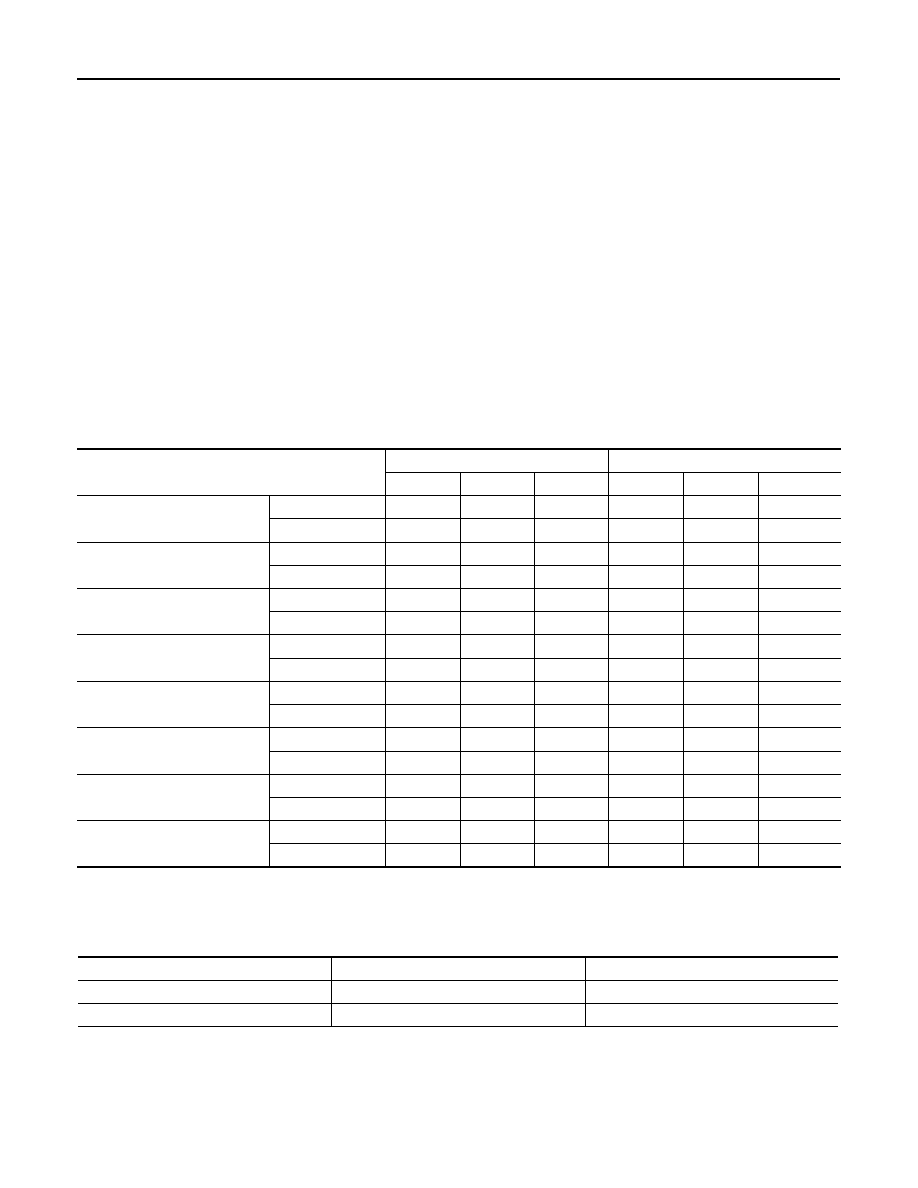
Test Item

SOLENOID VALVE

• When performing an active test of the ABS function, select the “MAIN SIGNALS” for each test item. In addi-

tion, when performing an active test of the VDC/TCS function, select the item menu for each test item.

• For ABS solenoid valve, touch “Up”, “Keep”, and “Down” on the display screen. For ABS solenoid valve

(ACT), touch “Up”, “ACT UP”, “ACT KEEP” and confirm that solenoid valves operate as shown in the table
below.

*: ON for 1 to 2 seconds after the touch, and then OFF

ABS MOTOR

• Touch “On” and “Off” on screen. Make sure motor relay and actuator relay operates as shown in table below.

Operation

ABS solenoid valve

ABS solenoid valve (ACT)

Up

Keep

Down

Up

ACT UP

ACT KEEP

FR RH SOL

FR RH IN SOL

Off

On

On

FR RH OUT SOL

Off

Off

On*

FR LH SOL

FR LH IN SOL

Off

On

On

FR LH OUT SOL

Off

Off

On*

RR RH SOL

RR RH IN SOL

Off

On

On

RR RH OUT SOL

Off

Off

On*

RR LH SOL

RR LH IN SOL

Off

On

On

RR LH OUT SOL

Off

Off

On*

FR RH ABS SOLENOID (ACT)

FR RH IN SOL

Off

Off

Off

FR RH OUT SOL

Off

Off

Off

FR LH ABS SOLENOID (ACT)

FR LH IN SOL

Off

Off

Off

FR LH OUT SOL

Off

Off

Off

RR RH ABS SOLENOID (ACT)

RR RH IN SOL

Off

Off

Off

RR RH OUT SOL

Off

Off

Off

RR LH ABS SOLENOID (ACT)

RR LH IN SOL

Off

Off

Off

RR LH OUT SOL

Off

Off

Off

Operation

On

Off

MOTOR RELAY

On

Off

ACTUATOR RLY

On

On

APPLICATION NOTICE

BRC-99

< COMPONENT DIAGNOSIS >

[TYPE 2]

C

D

E

G

H

I

J

K

L

M

A

B

BRC

N

O

P

COMPONENT DIAGNOSIS

APPLICATION NOTICE

Application Notice

INFOID:0000000005548388

Service information

Remarks

TYPE 1

ABS

TYPE 2

VDC/TCS/ABS

TYPE 3

HILL DESCENT CONTROL/HILL START ASSIST/VDC/TCS/ABS

BRC-100

< COMPONENT DIAGNOSIS >

[TYPE 2]

C1101, C1102, C1103, C1104 WHEEL SENSOR-1

C1101, C1102, C1103, C1104 WHEEL SENSOR-1

Description

INFOID:0000000005548242

When the sensor rotor rotates, the magnetic field changes. It converts the magnetic field changes to current
signals (rectangular wave) and transmits them to the ABS actuator and electric unit (control unit). 

DTC Logic

INFOID:0000000005548243

DTC DETECTION LOGIC

DTC CONFIRMATION PROCEDURE

1.

CHECK SELF-DIAGNOSIS RESULTS

Check the self-diagnosis results.

Is above displayed on the self-diagnosis display?

YES

>> Proceed to diagnosis procedure. Refer to 

BRC-100, "Diagnosis Procedure"

.

NO

>> Inspection End

Diagnosis Procedure

INFOID:0000000005548244

Regarding Wiring Diagram information, refer to 

BRC-154, "Wiring Diagram - BRAKE CONTROL SYSTEM -

WITHOUT HILL DESCENT CONTROL/HILL START ASSIST"

.

CAUTION:

Do not check between wheel sensor terminals.

1.

CONNECTOR INSPECTION

1.

Disconnect the ABS actuator and electric unit (control unit) connector and wheel sensor of malfunctioning
code. 

2.

Check the terminals for deformation, disconnection, looseness or damage.

Is the inspection result normal?

YES

>> GO TO 2

NO

>> Repair or replace as necessary.

2.

CHECK WHEEL SENSOR OUTPUT SIGNAL

1.

Connect ABS active wheel sensor tester (J-45741) to wheel sensor using appropriate adapter.

2.

Turn on the ABS active wheel sensor tester power switch.
NOTE:

DTC

Display item

Malfunction detected condition

Possible cause

C1101

RR RH SENSOR-1

Circuit of rear RH wheel sensor is open. Or when the sen-
sor power voltage is outside the standard.

• Harness or connector
• Wheel sensor
• ABS actuator and electric unit 

(control unit)

C1102

RR LH SENSOR-1

Circuit of rear LH wheel sensor is open. Or when the sen-
sor power voltage is outside the standard.

C1103

FR RH SENSOR-1

Circuit of front RH wheel sensor is open. Or when the 
sensor power voltage is outside the standard.

C1104

FR LH SENSOR-1

Circuit of front LH wheel sensor is open. Or when the 
sensor power voltage is outside the standard.

Self-diagnosis results

RR RH SENSOR-1

RR LH SENSOR-1

FR RH SENSOR-1

FR LH SENSOR-1

C1101, C1102, C1103, C1104 WHEEL SENSOR-1

BRC-101

< COMPONENT DIAGNOSIS >

[TYPE 2]

C

D

E

G

H

I

J

K

L

M

A

B

BRC

N

O

P

The green POWER indicator should illuminate. If the POWER indicator does not illuminate, replace the
battery in the ABS active wheel sensor tester before proceeding.

3.

Spin the wheel of the vehicle by hand and observe the red SENSOR indicator on the ABS active wheel
sensor tester. The red SENSOR indicator should flash on and off to indicate an output signal.
NOTE:
If the red SENSOR indicator illuminates but does not flash, reverse the polarity of the tester leads and
retest.

Does the ABS active wheel sensor tester detect a signal?

YES

>> GO TO 3

NO

>> Replace the wheel sensor. Refer to 

BRC-178, "Removal and Installation"

.

3.

CHECK TIRES

Check the inflation pressure, wear and size of each tire.

Is the inspection result normal?

YES

>> GO TO 4

NO

>> Adjust tire pressure or replace tire(s).

4.

CHECK WHEEL BEARINGS

Check wheel bearing axial end play. Refer to 

FAX-5, "On-Vehicle Inspection and Service"

 (front), 

RAX-6,

"Rear Axle Bearing"

 (C200 rear), or 

RAX-18, "Rear Axle Bearing"

 (M226 rear).

Is the inspection result normal?

YES

>> GO TO 5

NO

>> Repair or replace as necessary. Refer to 

FAX-8, "Removal and Installation"

 (front), 

RAX-12,

"Removal and Installation"

 (C200 rear), or 

RAX-23, "Removal and Installation"

 (M226 rear).

5.

CHECK WIRING HARNESS FOR SHORT CIRCUIT

1.

Disconnect ABS actuator and electric unit (control unit) connec-
tor and wheel sensor connector of malfunction code No.

2.

Check continuity between wheel sensor connector terminals
and ground.

Is the inspection result normal?

YES

>> GO TO 6

NO

>> Repair the circuit.

6.

CHECK WIRING HARNESS FOR OPEN CIRCUIT

1.

Check continuity between ABS actuator and electric unit (control unit) connector and the malfunctioning
wheel sensor connector.

Is the inspection result normal?

Continuity should not exist.

AWFIA0188ZZ

Wheel sensor

ABS actuator and 

electric unit (control unit)

Wheel sensor

Continuity

Connector

Terminal

Connector

Terminal

Front LH

E127

45

E18

1

Yes

46

2

Front RH

34

E117

1

33

2

Rear LH

36

C11

1

37

2

Rear RH

43

C10

1

42

2


Content   ..  98  99  100  101   ..