Nissan Terrano model r20 series 2004. Manual - part 435
System Description
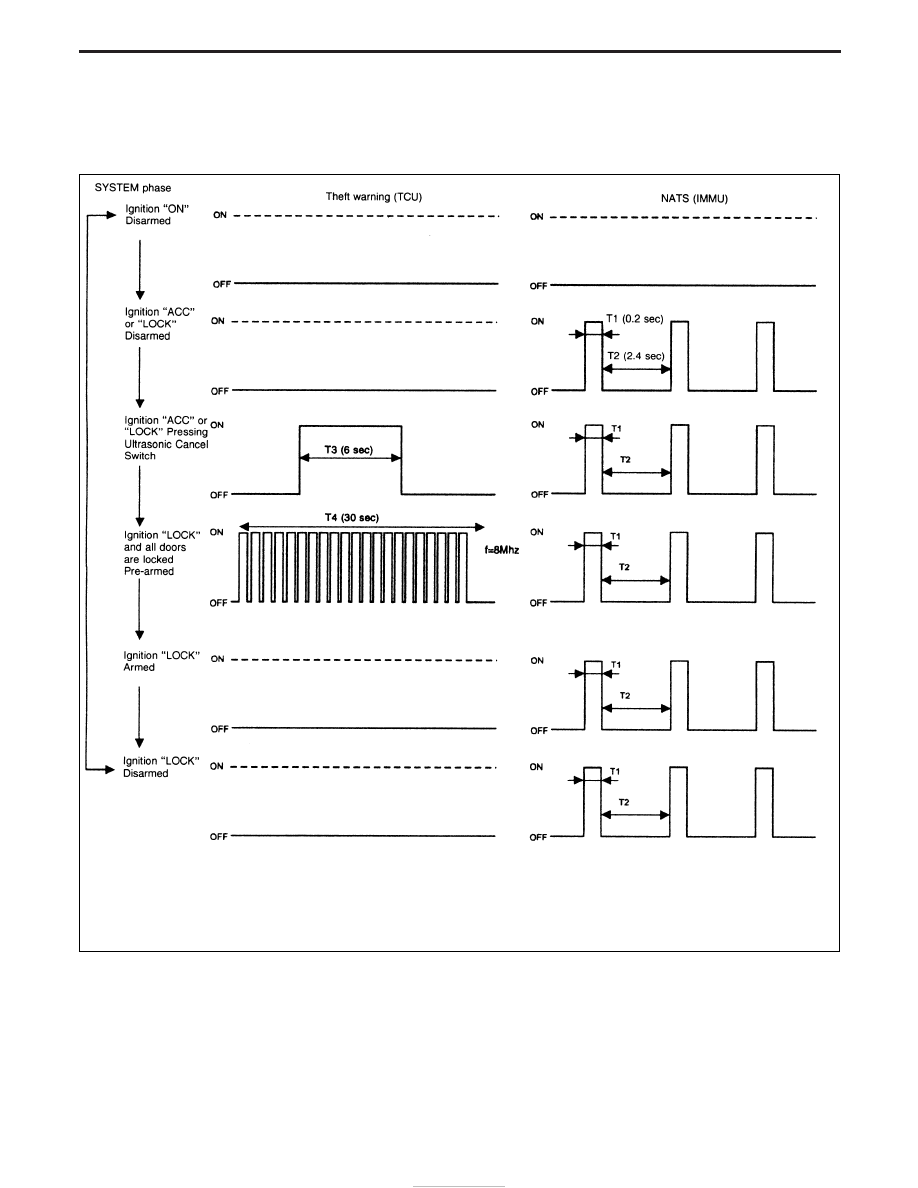
OPERATION FLOW
The SECURITY indicator can be operated by both the IMMU (for NATS) and the TCU (for Theft Warning). The
flow chart shows both operations.
NEL624
THEFT WARNING SYSTEM
EL-244