Nissan Terrano model r20 series 2004. Manual - part 357
How to Perform Trouble Diagnoses for Quick
and Accurate Repair
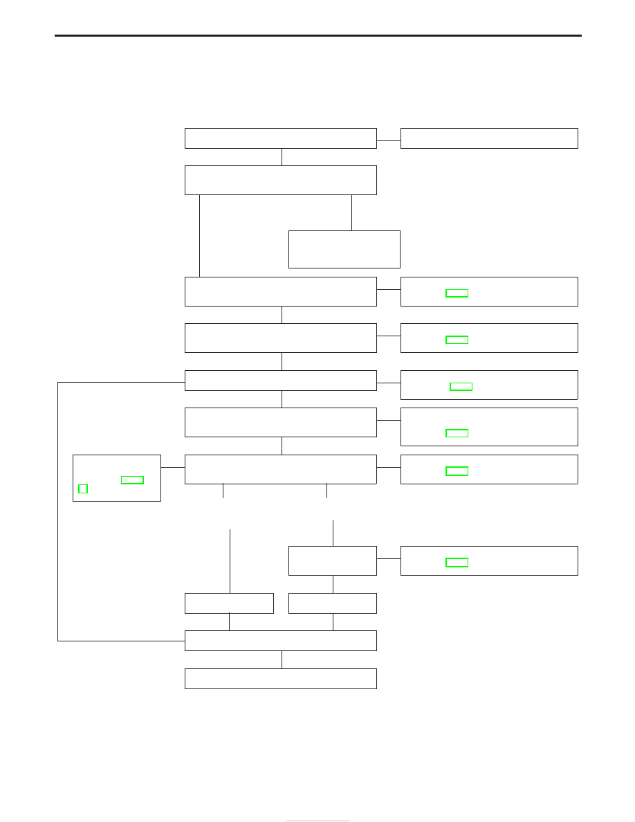
WORK FLOW
CHECK IN
F
Reference item
LISTEN TO CUSTOMER COMPLAINT AND CON-
FIRM BY PERFORMING OPERATIONAL CHECK.
Can be
confirmed
Cannot be
confirmed
EDUCATE CUSTOMER ON
CORRECT OPERATION OF
SYSTEM.
LISTEN TO CUSTOMER COMPLAINTS AND
CONFIRM.
F
Symptom Chart
(See page HA-37.)
INVESTIGATE ITEMS YOU SHOULD CARRY
OUT RELATED TO EACH SYMPTOM.
F
Symptom Chart
(See page HA-37.)
E
ELIMINATE GOOD SYSTEM(S)/PART(S).
F
Preliminary Check
(See pages HA-38.)
CHECK MAIN POWER SUPPLY AND GROUND
CIRCUITS.
F
Main Power Supply and Ground Circuit
Check
(See page HA-52.)
Diagnostic
Procedure(s)
(See pages HA-53 -
55.)
E
ELIMINATE GOOD PART(S)/HARNESS(ES)/
CONNECTOR(S) ELECTRICALLY.
F
Harness Layout for A/C System
(See page HA-40.)
Malfunctioning
harness(es)/
connector(s)
Malfunctioning
part(s)
INSPECT EACH
COMPONENT.
F
Electrical Components Inspection
(See page HA-61.)
REPAIR.
H
REPAIR/REPLACE.
NG
FINAL CHECK
OK
CHECK OUT
H
H
H
H
H
H
H
H
H
H
H
H
DIAGNOSES — Overall System
HA-28