Nissan Terrano model r20 series 2004. Manual - part 331


  Index      Nissan     Nissan Terrano model r20 series 2004 - Service and Repair Manual


Search            


Content   ..  329  330  331  332   ..


Nissan Terrano model r20 series 2004. Manual - part 331


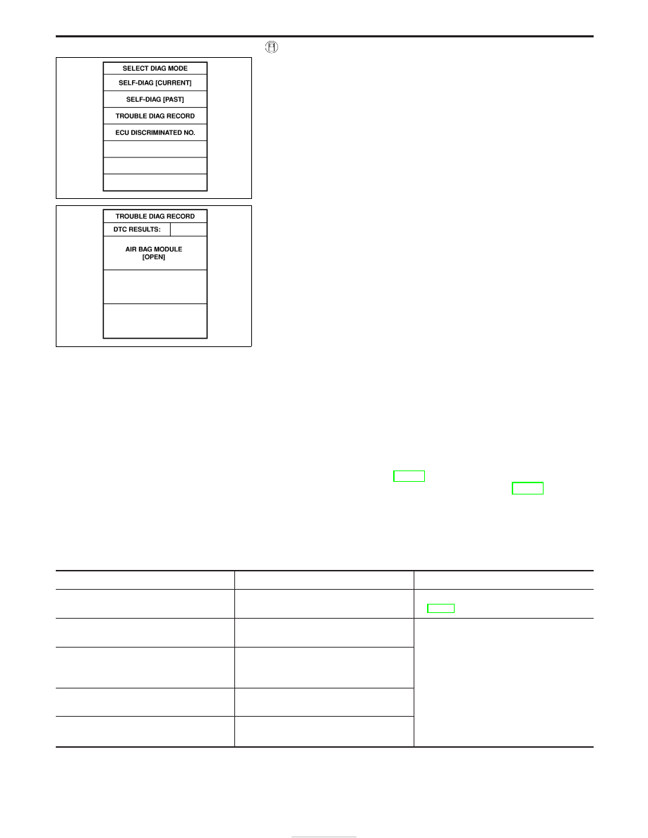
8. Touch “TROUBLE DIAG RECORD”.
NOTE:
With “TROUBLE DIAG RECORD”, diagnosis results previously
erased by a reset operation can be displayed.

9. Diagnostic code is displayed on “TROUBLE DIAG RECORD”.

10. Touch “PRINT”.
11. Compare diagnostic codes to “Intermittent Malfunction Diag-

nostic Code Chart”, page RS-53.

12. Touch “BACK” key of CONSULT-II until “SELECT SYSTEM”

appears.

13. Turn ignition switch “OFF”, then turn off and disconnect

CONSULT-II, and disconnect both battery cables.

14. Repair the system as outlined by the “Repair order” in “Inter-

mittent Malfunction Diagnostic Code Chart”, that corresponds
to the self-diagnostic result. For replacement procedure of com-
ponent parts, refer to RS-13.

15. Go to DIAGNOSTIC PROCEDURE 3, page RS-42, for final-

checking.

INTERMITTENT MALFUNCTION DIAGNOSTIC CODE
CHART (“SELF-DIAG [PAST] or TROUBLE DIAG
RECORD”)

Diagnostic item

Explanation

Repair order

NO DTC IS DETECTED.

I

No malfunction is detected.

I

Go to DIAGNOSTIC PROCEDURE 3
(RS-42).

AIRBAG MODULE
[OPEN]

I

Driver air bag module circuit is open.
(including the spiral cable)

1. Visually check the wiring harness con-

nection.

2. Replace the harness if it has visible

damage.

3. If the harness check is OK, replace the

spiral cable, diagnosis sensor unit and
driver air bag module. (Before disposing
of the driver air bag module, it must be
deployed.)

AIRBAG MODULE
[VB-SHORT]

I

Driver air bag module circuit is shorted
to a power supply circuit. (including the
spiral cable)

AIRBAG MODULE
[GND-SHORT]

I

Driver air bag module circuit is shorted
to ground. (including the spiral cable)

AIRBAG MODULE
[SHORT]

I

Driver air bag module circuit is shorted
between wires.

SRS697

SRS704

SUPPLEMENTAL RESTRAINT SYSTEM (SRS)

Trouble Diagnoses with CONSULT-II (Cont’d)

RS-46

Diagnostic item

Explanation

Repair order

ASSIST A/B MODULE
[VB-SHORT]

I

Front passenger air bag module circuit
is shorted to a power supply circuit.

1. Visually check the wiring harness con-

nection.

2. Replace the harness if it has visible

damage.

3. If the harness check is OK, replace the

diagnosis sensor unit and passenger air
bag module. (Before disposing of the
passenger air bag module, it must be
deployed.)

ASSIST A/B MODULE
[OPEN]

I

Front passenger air bag module circuit
is open.

ASSIST A/B MODULE
[GND-SHORT]

I

Front passenger air bag module circuit
is shorted to ground.

ASSIST A/B MODULE
[SHORT]

I

Front passenger air bag module circuit
is shorted between wires.

SIDE MODULE LH
[OPEN]

I

Front LH side air bag module circuit is
open.

1. Visually check the wiring harness con-

nection.

2. Replace the harness if it has visible

damage.

3. If the harness check is OK, replace the

diagnosis sensor unit and front LH side
air bag module. (Before disposing of the
front LH side air bag module, it must be
deployed.)

SIDE MODULE LH
[VB-SHORT]

I

Front LH side air bag module circuit is
shorted to a power supply circuit.

SIDE MODULE LH
[GND-SHORT]

I

Front LH side air bag module circuit is
shorted to ground.

SIDE MODULE LH
[SHORT]

I

Front LH side air bag module circuit is
shorted between wires.

SIDE MODULE RH
[OPEN]

I

Front RH side air bag module circuit is
open.

1. Visually check the wiring harness con-

nection.

2. Replace the harness if it has visible

damage.

3. If the harness check is OK, replace the

diagnosis sensor unit and front RH side
air bag module. (Before disposing of the
front RH side air bag module, it must be
deployed.)

SIDE MODULE RH
[VB-SHORT]

I

Front RH side air bag module circuit is
shorted to a power supply circuit.

SIDE MODULE RH
[GND-SHORT]

I

Front RH side air bag module circuit is
shorted to ground.

SIDE MODULE RH
[SHORT]

I

Front RH side air bag module circuit is
shorted between wires.

SATELLITE SENS LH
[UNIT FAIL]
SATELLITE SENS LH
[COMM FAIL]

I

LH side air bag (satellite) sensor

1. Visually check the wiring harness con-

nection.

2. Replace the harness if it has visible

damage.

3. If the harness check is OK, replace the

diagnosis sensor unit and LH side air
bag (satellite) sensor.

SATELLITE SENS RH
[UNIT FAIL]
SATELLITE SENS RH
[COMM FAIL]

I

RH side air bag (satellite) sensor

1. Visually check the wiring harness con-

nection.

2. Replace the harness if it has visible

damage.

3. If the harness check is OK, replace the

diagnosis sensor unit and RH side air
bag (satellite) sensor.

PRE-TEN FRONT LH
[OPEN/VB-SHORT]

I

The circuit for front LH seat belt pre-
tensioner is open or shorted to a power
supply circuit.

1. Visually check the wiring harness con-

nections.

2. Replace the harness if it has visible

damage.

3. If the harness check is OK, replace the

diagnosis sensor unit and front LH seat
belt. (Before disposing of the front LH
seat belt pre-tensioner, if must be
deployed.)

PRE-TEN FRONT LH
[GND-SHORT]

I

The circuit for front LH seat belt pre-
tensioner is shorted to ground.

SUPPLEMENTAL RESTRAINT SYSTEM (SRS)

Trouble Diagnoses with CONSULT-II (Cont’d)

RS-47

Diagnostic item

Explanation

Repair order

PRE-TEN FRONT RH
[OPEN/VB-SHORT]

I

The circuit for front RH seat belt pre-
tensioner is open or shorted to a power
supply circuit.

1. Visually check the wiring harness con-

nections.

2. Replace the harness if it has visible

damage.

3. If the harness check is OK, replace the

diagnosis sensor unit and front RH seat
belt. (Before disposing of the front RH
seat belt pre-tensioner, if must be
deployed.)

PRE-TEN FRONT RH
[GND-SHORT]

I

The circuit for front RH seat belt pre-
tensioner is shorted to ground.

CONTROL UNIT

I

Diagnosis sensor unit is malfunctioning.

1. Visually check the wiring harness con-

nection.

2. Replace the harness if it has visible

damage.

3. If the harness check is OK, replace the

diagnosis sensor unit.

* Follow the procedures in numerical order when repairing malfunctioning parts, then make the final system check.

Trouble Diagnoses without CONSULT-II

DIAGNOSTIC PROCEDURE 6

Inspecting SRS malfunctioning parts by using “AIR BAG”
warning lamp — Diagnosis mode
NOTE:
SRS will not enter Diagnosis mode if no malfunction is
detected in User mode.
1. Turn ignition switch “ON”.
2. After “AIR BAG” warning lamp lights for 7 seconds, turn ignition

switch “OFF” within 1 second.

3. Wait more than 3 seconds.
4. Repeat steps 1 to 3 three times.
5. Turn ignition switch “ON”.

SRS is now in Diagnosis mode.

6. “AIR BAG” warning lamp operates in Diagnosis mode as fol-

lows:

NOTE:
If SRS does not enter Diagnosis mode even though malfunc-
tion is detected in User mode, check the battery voltage.
If the battery voltage is less than 9V, charge the battery. Then
go to DIAGNOSTIC PROCEDURE 7, page RS-53.
If the battery voltage is OK, replace the diagnosis sensor unit.

SRS800

SUPPLEMENTAL RESTRAINT SYSTEM (SRS)

Trouble Diagnoses with CONSULT-II (Cont’d)

RS-48

No.

“AIR BAG” warning lamp flash pattern — Diagnosis mode —

SRS condition

1

SRS333

q

a

through

q

b

are repeated.

I

Diagnosis
results (pre-
viously
stored in the
memory)
might not be
erased after
repair.

I

Intermittent
malfunction
has been
detected in
the past.

Go to DIAG-
NOSTIC PRO-
CEDURE 8
(RS-56).

2

SRS341

q

a

through

q

d

are repeated.

q

b

— Driver and front pas-

senger air bag and front seat
belt pre-tensioner marker
(For identifying driver air bag,
front passenger air bag
and/or front seat belt pre-
tensioners malfunctioning)

q

d

— Indicates malfunction-

ing part. The number of flash
varies with malfunctioning
part (0.5 sec. ON and 0.5
sec. OFF is counted as one
flash.)

The system is
malfunctioning
and needs to
be repaired.

3

SRS342-A

q

a

through

q

f

are repeated.

q

b

,

q

c

,

q

d

— Front side air

bag marker (For identifying
front side air bag malfunc-
tioning)

q

f

— Indicates malfunctioning

part. The number of flash
varies with malfunctioning
part (0.5 sec. ON and 0.5
sec. OFF is counted as one
flash.)

7. Malfunctioning part is indicated by the number of flashes (part

q

d

or

q

f

). Compare the number of flashes to “Air Bag Warning

Lamp Flash Code Chart”, page RS-50, and locate malfunction-
ing part.

8. Turn ignition switch “OFF”, and disconnect both battery cables.
9. Repair the system as outlined by the “Repair order” in “Warn-

ing Lamp Flash Code Chart” that corresponds to the flash code.
For replacement procedure of component parts, refer to RS-21.

10. After repairing the system, go to DIAGNOSTIC PROCEDURE

7, page RS-53.

SUPPLEMENTAL RESTRAINT SYSTEM (SRS)

Trouble Diagnoses without CONSULT-II

(Cont’d)

RS-49


Content   ..  329  330  331  332   ..