Nissan Terrano model r20 series 2004. Manual - part 330


  Index      Nissan     Nissan Terrano model r20 series 2004 - Service and Repair Manual


Search            


Content   ..  328  329  330  331   ..


Nissan Terrano model r20 series 2004. Manual - part 330


Diagnostic item

Explanation

Repair order

“Recheck SRS at each replacement.”

PRE-TEN FRONT RH
[OPEN/VB-SHORT]

I

The circuit for front RH seat belt pre-tensioner is open or
shorted to a power supply circuit.

1. Visually check the wiring harness

connections.

2. Replace the harness if it has visible

damage.

3. Replace front RH seat belt.

(Before disposal, it must be deacti-
vated.)

4. Replace the diagnosis sensor unit.
5. Replace the related harness.

PRE-TEN FRONT RH
[GND-SHORT]

I

The circuit for front RH seat belt pre-tensioner is shorted to
ground.

INDEFINITE FAIL-
URES (AIR BAG)

I

A problem which cannot be specified occurs because more
than two parts are out of order.

1. Visually check wiring harness con-

nections.

2. Replace diagnosis sensor unit.
3. Replace spiral cable and air bag

modules.

4. Replace air bag and pre-tensioner

harness.

5. Replace main harness.

INDEFINITE FAIL-
URES
(PRE-TENSIONER)

Driver’s and front passenger seat belt pre-tensioners are out of
order.

1. Visually check wiring harness con-

nections.

2. Replace diagnosis sensor unit.
3. Replace spiral cable and air bag

modules.

4. Replace air bag and pre-tensioner

harness.

5. Replace main harness.

CONTROL UNIT

I

Low battery voltage (Less than 9V)

I

Go to DIAGNOSTIC PROCEDURE 3
(RS-42) after charging battery.

I

Diagnosis sensor unit is malfunctioning.

1. Visually check the wiring harness

connection.

2. Replace the harness if it has visible

damage.

3. Replace diagnosis sensor unit.
4. Replace the related harness.

* Follow the procedures in numerical order when repairing malfunctioning parts. Confirm whether malfunction is eliminated using the
air bag warning lamp or CONSULT-II each time repair is finished. If malfunction is still observed, proceed to the next step. When mal-
function is eliminated, further repair work is not required.

DIAGNOSTIC PROCEDURE 3

Final checking after repairing SRS by using CONSULT-II —
Diagnosis mode
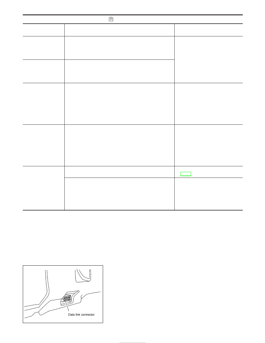
1. After repairing SRS, connect both battery cables.
2. Connect CONSULT-II to data link connector.
3. Turn ignition switch from “OFF” to “ON”.

NRS122

SUPPLEMENTAL RESTRAINT SYSTEM (SRS)

Trouble Diagnoses with CONSULT-II (Cont’d)

RS-42

4. Touch “START”.

5. Touch “AIR BAG”.

6. Touch “SELF-DIAG [CURRENT]”.

7. If no malfunction is detected on “SELF-DIAG [CURRENT]”,

repair of SRS is completed. Go to step 8.
If any malfunction is displayed on “SELF-DIAG [CURRENT]”,
the malfunctioning part is not repaired completely or another
malfunctioning part is detected. Go to DIAGNOSTIC PROCE-
DURE 2, page RS-39, and repair malfunctioning part com-
pletely.

8. Touch “ERASE”.
NOTE:
Touch “ERASE” to clear the memory of the malfunction
(“SELF-DIAG [PAST]”).
If the memory of the malfunction in “SELF-DIAG [PAST]” is not
erased, the User mode shows the system malfunction by the opera-
tion of the warning lamp even if the malfunction is repaired com-
pletely.

SRS695

C2SSE01

SRS697

SRS701

SRS773

SUPPLEMENTAL RESTRAINT SYSTEM (SRS)

Trouble Diagnoses with CONSULT-II (Cont’d)

RS-43

9. Touch “BACK” key of CONSULT-II to “SELECT SYSTEM”

screen. Touch “SELF-DIAG [PAST]”.

10. Check that no malfunction is detected on “SELF-DIAG [PAST]”.

11. Touch “BACK” key of CONSULT-II until “SELECT SYSTEM”

appears in order to return to User mode from Diagnosis mode.

12. Turn ignition switch “OFF”, then turn off and disconnect CON-

SULT-II.

13. Go to “SRS Operation Check”, page RS-38 to check SRS

operation by using “AIR BAG” warning lamp with User mode.

DIAGNOSTIC PROCEDURE 4 (CONTINUED FROM
DIAGNOSTIC PROCEDURE 2)

Inspecting SRS malfunctioning record

1

CONSIDER POSSIBILITY OF NOT ERASING SELF-DIAGNOSTIC RESULT AFTER REPAIRING

Is it the first time for maintenance of SRS?

Yes or No

Yes

E

Go to DIAGNOSTIC PROCEDURE 5 (RS-44).

No

E

Self-diagnostic result “SELF-DIAG [PAST]” (previously stored in the memory) might not be erased after repair. Go
to DIAGNOSTIC PROCEDURE 3, step 8 (RS-42).

DIAGNOSTIC PROCEDURE 5

Inspecting SRS intermittent malfunction by using CONSULT-II
— Diagnosis mode
1. Turn ignition switch “OFF”.
2. Connect CONSULT-II to data link connector.

SRS697

SRS702

NRS122

SUPPLEMENTAL RESTRAINT SYSTEM (SRS)

Trouble Diagnoses with CONSULT-II (Cont’d)

RS-44

3. Turn ignition switch “ON”.
4. Touch “START”.

5. Touch “AIR BAG”.

6. Touch “SELF-DIAG [PAST]”.

7. If diagnostic codes are displayed on “SELF-DIAG [PAST]”, go

to step 10.

If no malfunction is detected on “SELF-DIAG [PAST]”, touch
“BACK” and go back to “SELECT DIAG MODE”.

SRS695

C2SSE01

SRS697

SRS700

SRS702

SUPPLEMENTAL RESTRAINT SYSTEM (SRS)

Trouble Diagnoses with CONSULT-II (Cont’d)

RS-45


Content   ..  328  329  330  331   ..