Nissan Terrano model r20 series 2004. Manual - part 314
Inspection and Adjustment
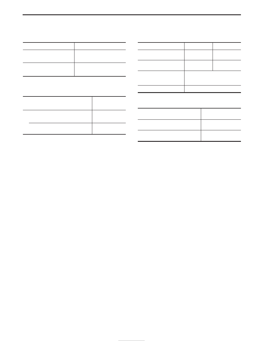
DISC BRAKE
Unit: mm (in)
Brake model
LD28VA
Pad wear limit
Minimum thickness
2.0 (0.079)
Rotor repair limit
Minimum thickness
24.0 (0.94)
DRUM BRAKE
Unit: mm (in)
Lining wear limit
Minimum thickness
1.52 (0.06)
Drum repair limit
Maximum inner diameter
280.5 (11.04)
Out-of-roundness
0.05 (0.0020)
or less
BRAKE PEDAL
Unit: mm (in)
RHD
LHD
Free pedal height (H)
196 - 206
(7.7 - 8.1)
210 - 220
(8.3 - 8.7)
Full stroke (D)
137.7 - 147.7
(5.42 - 5.81)
142.5 - 152.5
(5.61 - 6.0)
Clearance between pedal
stopper and threaded end of
stop lamp switch (C)
0.3 - 1.0 (0.012 - 0.039)
Pedal free play at clevis (A)
1 - 3 (0.039 - 0.118)
PARKING BRAKE
Control type
Item
Center lever
Number of notches
[under force of 196 N (20 kg, 44 lb)]
9 - 10
Number of notches
(when warning switch comes on)
1
SERVICE DATA AND SPECIFICATIONS (SDS)
BR-86