Nissan Terrano model r20 series 2004. Manual - part 313


  Index      Nissan     Nissan Terrano model r20 series 2004 - Service and Repair Manual


Search            


Content   ..  311  312  313  314   ..


Nissan Terrano model r20 series 2004. Manual - part 313


Diagnostic Procedure 12 (Unexpected pedal
action)

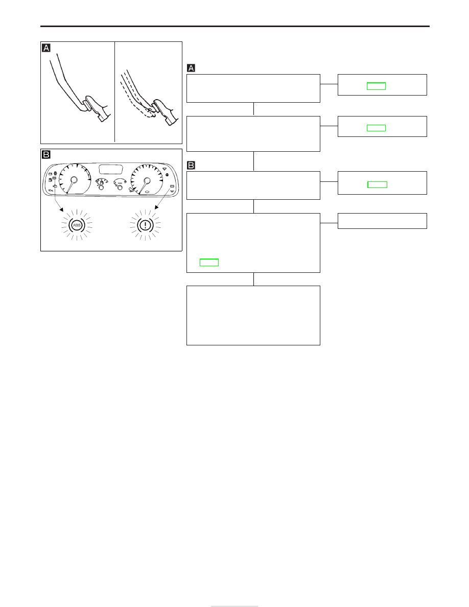
CHECK BRAKE PEDAL STROKE.
Check brake pedal stroke. Is stroke exces-
sively large?

No

E

Yes

Perform Preliminary Check.
Refer to BR-66.

CHECK BRAKE PERFORMANCE
Disconnect ABS actuator and electric unit
connector and check whether brake is
effective.

Yes

E

No

Perform Preliminary Check.
Refer to BR-66.

CHECK IF WARNING LAMP ACTIVATES.
Ensure warning lamp remains off while
driving.

OK

E

NG

Carry out self-diagnosis.
Refer to BR-60.

CHECK WHEEL SENSOR.
1. Check wheel sensor connector for ter-

minal damage or loose connection.

2. Perform wheel sensor mechanical

check.
Refer to Diagnostic Procedure 4,
BR-74.

OK

E

NG

Repair.

CHECK HARNESS CONNECTOR.
Check ABS actuator and electric unit pin
terminals for damage or the connection of
ABS actuator and electric unit harness
connector.
Reconnect ABS actuator and electric unit
harness connector. Then retest.

CAUTION:

Drive at low speed and brake smoothly to prevent

rear wheels locking.

SBR540A

YBR279

H

H

H

H

TROUBLE DIAGNOSES

BR-82

Diagnostic Procedure 13

SYMPTOM: ABS does not work.

Does the ABS warning lamp activate?

No

E

Yes

Carry out self-diagnosis.
Refer to BR-60.

Go to

in Diagnostic Procedure 12,

BR-82.

Note: ABS does not work when vehicle speed is under 10 km/h

(6 MPH).

Diagnostic Procedure 14

SYMPTOM: ABS works frequently.

CHECK WHEEL SENSOR.
1. Check wheel sensor connector for ter-

minal damage or loose connections.

2. Perform wheel sensor mechanical

check.
Refer to Diagnostic Procedure 4,
BR-74.

OK

E

NG

Repair.

CHECK FRONT AXLES
Check front axles for excessive loose-
ness. Refer to FA section (“Front Wheel
Bearing”, “ON-VEHICLE SERVICE”).

OK

E

NG

Repair.

Go to

in Diagnostic Procedure 12,

BR-82.

H

H

H

TROUBLE DIAGNOSES

BR-83

Electrical Components Inspection

WHEEL SENSOR

Check resistance for each sensor.

Resistance:

Front 0.9 - 1.1 k

Rear 1.44 - 1.76 k

G SENSOR

Condition

Resistance between ter-

minals

q

3

and

q

4

Continuity

Installed in vehicle

Approx. 1.5 k

Yes

Tilted as shown in figure

Approx. 5.1 k

No

YBR085

YBR280

TROUBLE DIAGNOSES

BR-84

General Specifications

Applied model

Wagon (LWB)

Hard Top (SWB)

Wagon (LWB)

Hard Top (SWB)

Without ABS

With ABS

Front brake

LD28VA

Brake model

Cylinder bore diameter

mm (in)

43 (1.69)

Pad

mm (in)

length x width x thickness

144.85 x 48.5 x 15.5

(5.70 x 1.90 x 0.61)

Rotor

mm (in)

outer diameter x thickness

276.7 x 26.1

(10.89 x 1.02)

Drum brake

LT28

Brake model

Cylinder bore diameter

mm (in)

23.8 (0.94)

22.0 (0.87)

20.6 (0.81)

Lining

mm (in)

Length x width x thickness

Leading

111 x 55 x 8.95 (4.37 x 2.17 x 0.35)

Trailing

114 x 55 x 3.95 (4.49 x 2.17 x 0.16)

Drum inner

mm (in)

Diameter

280 (11.02)

Master cylinder

mm (in)

Cylinder bore diameter

25.4 (1.0)

Control valve

Valve model

Load Sensing Valve

Split point [kPa (bar, kg/cm

2

, psi)] x

reducing ratio

Variable x 0.23

Variable x 0.15

Brake booster

Booster model

Lucas LSC 115 (8

+ 9

)

Diaphragm diameter

mm (in)

Primary: 203.2 (8)

Secondary: 228.6 (9)

Specified brake fluid

DOT 4

SERVICE DATA AND SPECIFICATIONS (SDS)

BR-85


Content   ..  311  312  313  314   ..