Nissan Terrano model r20 series 2004. Manual - part 268
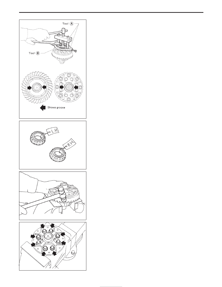
Differential Case
1. Remove side bearing inner cones.
To prevent damage to bearing, engage puller jaws in grooves.
Assembly:
ST33065001
Tool number:
q
A
ST33051001
q
B
ST33061000
Be careful not to confuse the right and left hand parts.
2. Loosen ring gear bolts in a criss-cross fashion.
3. Tap ring gear off differential case with a soft hammer.
Tap evenly all around to keep ring gear from binding.
4. Separate L.H. and R.H. differential cases.
Put match marks on both L.H. and R.H. differential cases.
SPD642
SPD022
SPD024
SPD643
DISASSEMBLY (R180A)
PD-18