Nissan Terrano model r20 series 2004. Manual - part 243
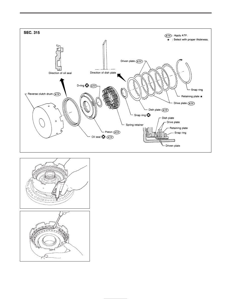
Reverse Clutch
DISASSEMBLY
1. Check operation of reverse clutch.
a. Install seal ring onto oil pump cover and install reverse clutch.
Apply compressed air to oil hole.
b. Check to see that retaining plate moves to snap ring.
c. If retaining plate does not contact snap ring,
I
D-ring might be damaged.
I
Oil seal might be damaged.
I
Fluid might be leaking past piston check ball.
2. Remove drive plates, driven plates, retaining plate, dish plate
and snap ring.
NAT296
SAT841A
SAT842A
REPAIR FOR COMPONENT PARTS
AT-156