Nissan Terrano model r20 series 2004. Manual - part 195
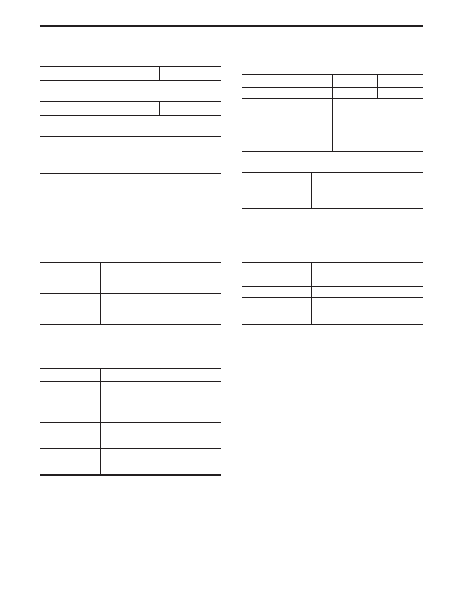
General Specifications
CLUTCH CONTROL SYSTEM
Type of clutch control
Hydraulic
CLUTCH MASTER CYLINDER
Inner diameter
mm (in)
15.87 (5/8)
CLUTCH OPERATING CYLINDER
Inner diameter
mm (in)
LHD
17.46 (11/16)
RHD
19.05 (3/4)
CLUTCH DISC
Unit: mm (in)
Engine
TD27Ti
ZD30DDTi
Model
250
260
Facing size
(Outer dia. x inner dia. x
thickness)
250 x 160 x 3.7
(9.84 x 6.30 x 0.1457)
Thickness of disc assembly
under load
7.0 - 7.4 (0.276 - 0.291)
Under a load of 5,884 N
(600 kg, 1,323 lb)
CLUTCH COVER
Engine
TD27Ti
ZD30DDTi
Model
250
260
Full load
N (kg, lb)
5,884 (600, 1,323)
6,760 (689, 1,520)
Inspection and Adjustment
CLUTCH PEDAL
Unit: mm (in)
Handle
LHD
RHD
Pedal height*
227 - 237
(8.94 - 9.33)
210 - 220
(8.27 - 8.66)
Pedal stroke
155 - 160 (6.10 - 6.30)
Pedal free play
(Backlash at clevis)
1.0 - 3.0 (0.039 - 0.118)
*: Measured from surface of melt sheet to surface of pedal
pad
CLUTCH DISC
Unit: mm (in)
Engine
TD27Ti
ZD30DDTi
Disc model
250
260
Rear limit of facing
surface to rivet head
0.3 (0.012)
Runout limit of facing
1 (0.04)
Distance of runout
check point (from the
hub center)
120 (4.72)
Maximum of spline
backlash of spline (at
outer edge of disc)
1.0 (0.039)
CLUTCH COVER
Unit: mm (in)
Engine
TD27Ti
ZD30DDTi
Cover model
250
260
Diaphragm spring height
36.5 - 38.5 (1.437 - 1.516)
Uneven limit of dia-
phragm spring toe height
“A”
0.7 (0.028)
SERVICE DATA AND SPECIFICATIONS (SDS)
CL-14