Nissan Terrano model r20 series 2004. Manual - part 182


  Index      Nissan     Nissan Terrano model r20 series 2004 - Service and Repair Manual


Search            


Content   ..  180  181  182  183   ..


Nissan Terrano model r20 series 2004. Manual - part 182


Component Description

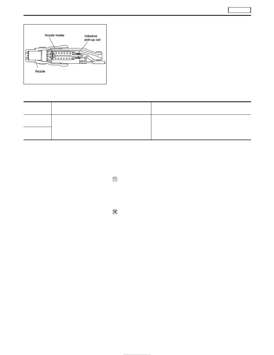
NEEDLE LIFT SENSOR (NLS)

The needle lift sensor is built into the No. 1 nozzle. Its inductive
pickup element senses fuel injection timing. It is sent as a pulse
signal to the ECM for feed-back the actual fuel injection timing and
calculating the secondary engine speed.

On Board Diagnosis Logic

DTC

Malfunction is detected when ....

Check Items

(Possible Cause)

P1240
0304

I

An incorrect signal from the sensor is sent to ECM.

I

Harness or connectors
(The sensor circuit is open or short-circuited.)

I

Needle lift sensor

P1242
0906

DTC Confirmation Procedure

NOTE:
Before DTC confirmation, be sure to check battery voltage is
above 9V.

WITH CONSULT-II

1) Turn ignition switch to “ON” position and select “DATA MONI-

TOR” mode with CONSULT-II.

2) Start engine.
3) Run it for 2 seconds at above 1,200 rpm.

WITHOUT CONSULT-II

1) Start engine.
2) Run it for 2 seconds at above 1,200 rpm.
3) Turn ignition switch to “LOCK” position, wait at least 5 seconds

and then turn to “ON” position.

4) Perform “Diagnostic Test Mode II” (Self-diagnostic results).

NEF689

DTC P1240 NEEDLE LIFT SEN, DTC P1242 NEEDLE LIFT SE

(RPM)

TD27Ti

EC-450

Wiring Diagram

YEC682A

DTC P1240 NEEDLE LIFT SEN, DTC P1242 NEEDLE LIFT SE

(RPM)

TD27Ti

EC-451

Diagnostic Procedure

INSPECTION START

CHECK FOR AIR IN FUEL FILTER.
1. Move priming pump up and down to

purge air from fuel filter.

2. Perform “DIAGNOSTIC TROUBLE

CODE CONFIRMATION PROCE-
DURE”.

CHECK INPUT SIGNAL CIRCUIT.
1. Turn ignition switch to “LOCK” position.
2. Disconnect ECM harness connector

and needle lift sensor harness connec-
tor.

3. Check harness continuity between

needle lift sensor connector terminal

q

1

and ECM connector terminal

345

.

Refer to wiring diagram.
Continuity should exist.
If OK, check harness for short-circuit.

OK

E

NG

Check the following:

I

Harness for open circuit
between needle lift sen-
sor and ECM

If NG, repair harness or
connectors.

CHECK GROUND CIRCUIT-I.
Check harness continuity between needle
lift sensor connector terminals

q

2

and

ECM connector terminals

333

. Refer to

wiring diagram.
Continuity should exist.
If OK, check harness for short-circuit.

OK

E

NG

Check the following:

I

Harness for open or
short-circuit between
ECM and needle lift sen-
sor.

If NG, repair harness or
connectors.

CHECK GROUND CIRCUIT-II.
Check resistance between ECM connector
terminal

346

and engine ground. Refer to

wiring diagram.
Continuity should exist.
If OK, check harness for short-circuit.

OK

E

NG

Check the following:

I

Harness for open-circuit
between ECM and
engine ground

If NG, repair harness or
connectors.

CHECK NO. 1 INJECTION NOZZLE FOR
CLOGGING.
Refer to spray pattern test of “INJECTION
NOZZLE”.
If NG, replace No. 1 injection nozzle.

q

A

NEF591

NEF690

NEF463

H

H

H

H

H

H

DTC P1240 NEEDLE LIFT SEN, DTC P1242 NEEDLE LIFT SE

(RPM)

TD27Ti

EC-452

q

A

CHECK COMPONENT.
(Needle lift sensor)
Refer to “COMPONENT INSPECTION” on
EC-453.

E

NG

Replace needle lift sensor.

Disconnect and reconnect harness con-
nectors in the circuit. Then retest.

Trouble is not fixed.

Check ECM pin terminals for damage and
check the connection of ECM harness
connector. Reconnect ECM harness con-
nector and retest.

INSPECTION END

Component Inspection

NEEDLE LIFT SENSOR

1. Disconnect needle lift sensor harness connector.
2. Check continuity between needle lift sensor terminals

q

1

and

q

2

.

Resistance: Approximately 105

[at 25°C (77°F)]

If NG, replace needle lift sensor with injection nozzle holder.

MEC962D

H

H

H

H

DTC P1240 NEEDLE LIFT SEN, DTC P1242 NEEDLE LIFT SE

(RPM)

TD27Ti

Diagnostic Procedure (Cont’d)

EC-453


Content   ..  180  181  182  183   ..