Index Nissan Nissan Terrano model r20 series 2004 - Service and Repair Manual
Search
Content .. 177 178 179 180 ..
Nissan Terrano model r20 series 2004. Manual - part 179
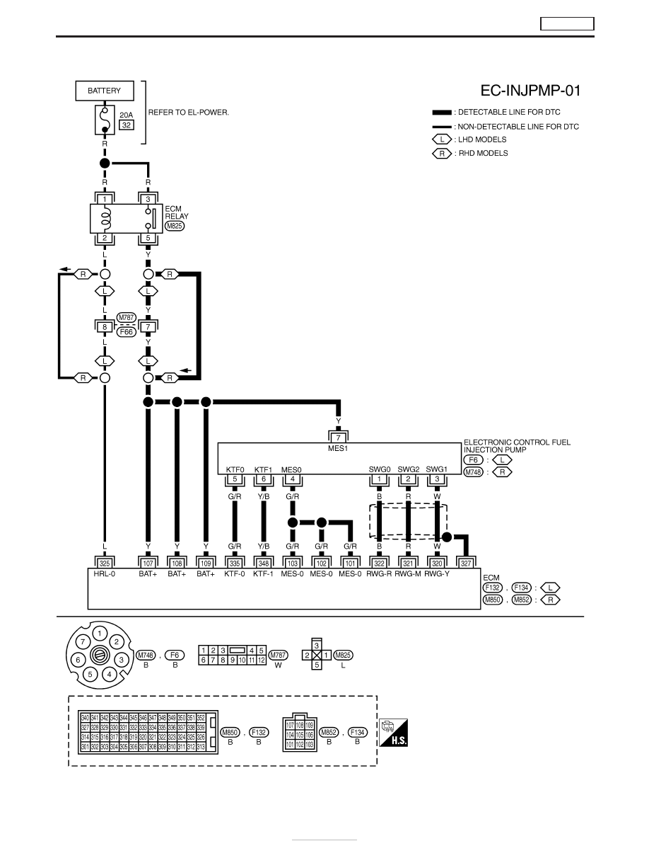
Wiring Diagram
YEC677A
DTC P1207 CONT SLEEV POS SEN
TD27Ti
EC-438