Nissan Terrano model r20 series 2004. Manual - part 171
Diagnostic Procedure
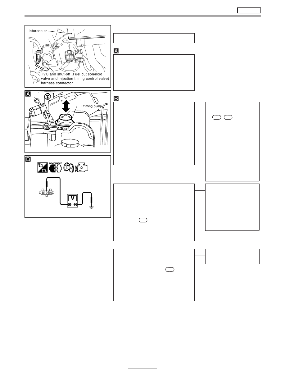
INSPECTION START
CHECK FOR AIR IN FUEL FILTER.
1. Move priming pump up and down to
purge air from fuel filter.
2. Perform “DIAGNOSTIC TROUBLE
CODE CONFIRMATION PROCE-
DURE”.
CHECK POWER SUPPLY.
1. Turn ignition switch to “LOCK” position.
2. Disconnect TVC and shut-off (injection
timing control valve) harness connec-
tor.
3. Turn ignition switch to “ON” position.
4. Check voltage between TVC and shut-
off (injection timing control valve) con-
nector terminal
q
9
and engine ground
with CONSULT-II or tester.
Voltage: Battery voltage
OK
E
NG
Check the following:
I
Harness connector
M787
,
F66
I
20A fuse
I
ECM relay
I
Harness for open or
short-circuit between
TVC and shut-off (injec-
tion timing control valve)
harness connector and
fuse box.
If NG, replace 20A fuse or
ECM relay, harness or con-
nectors.
CHECK OUTPUT SIGNAL CIRCUIT.
1. Turn ignition switch to “LOCK” position.
2. Disconnect ECM harness connector.
3. Check harness continuity between TVC
and shut-off (injection timing control
valve) connector terminal
q
8
and ECM
terminals
202
. Refer to wiring dia-
gram.
Continuity should exist.
If OK, check harness for short-circuit.
OK
E
NG
Check the following:
I
Harness for open or
short-circuit between
TVC and shut-off (injec-
tion timing control valve)
and ECM
If NG, repair harness or
connectors.
CHECK GROUND CIRCUIT.
1. Disconnect ECM harness connector.
2. Check harness continuity between
ECM connector terminal
349
and TVC
and shut-off (injection timing control
valve) connector terminal
q
10
. Refer to
wiring diagram.
Continuity should exist.
If OK, check harness of short-circuit.
OK
E
NG
Repair harness or connec-
tors
q
A
YEC256A
NEF463
MEC947D
H
H
H
H
H
DTC P0216 INJ TIMING CONT/V, DTC P1246 F/INJ TIMG F/B
TD27Ti
EC-406