Nissan Terrano model r20 series 2004. Manual - part 155


  Index      Nissan     Nissan Terrano model r20 series 2004 - Service and Repair Manual


Search            


Content   ..  153  154  155  156   ..


Nissan Terrano model r20 series 2004. Manual - part 155


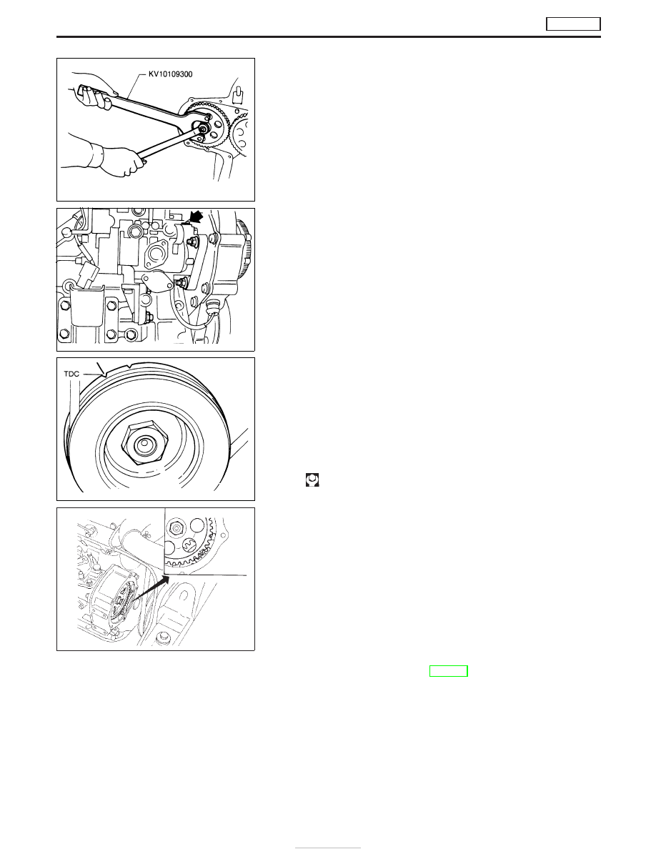
4. Remove dust cover and injection pump gear.

Refer to EM section.

5. Remove fixing nuts and bolts. Then remove injection pump.

Installation

Install injection pump assembly in the reverse order of removal,
observing the following:
1. Confirm that No. 1 cylinder is set at TDC on its compression

stroke.

2. Install injection pump (Refer to EM section).
(1) Temporarily set injection pump so that the flange of the pump

is aligned with aligning mark on front cover.

(2) Install injection pump gear.

: 59 - 69 N

m (6 - 7 kg-m, 43 - 51 ft-lb)

Make sure that the key does not fall into the front cover.
Make sure that “Z” marks are aligned.
(3) Apply liquid gasket to mating surface of injection pump gear

cover and install it.

3. Adjust injection timing.

Refer to “Basic Inspection”, EC-361.

4. Install all parts removed.

SEM653B

EEF160

EEF181

SEF337F

ELECTRONIC FUEL INJECTION PUMP

TD27Ti

Removal (Cont’d)

EC-342

Disassembly and Assembly

CAUTION:

I

Do not disassemble the parts not shown in the illustration
above.

I

Before installing injection timing control valve, smear a
coat of diesel fuel to O-ring and its mating area. Insert
injection timing control valve straight into bore in fuel
pump body. After positioning the injection timing control
valve correctly, visually check that the fuel does not leak.

I

After re-assembling the parts, erase Diagnostic Trouble
Code (DTC), and perform DTC CONFIRMATION PROCE-
DURE (or OVERALL FUNCTION CHECK).

YEC236A

ELECTRONIC FUEL INJECTION PUMP

TD27Ti

EC-343

DTC and MI Detection Logic

When a malfunction is detected for the first time, the malfunction (DTC) is stored in the ECM memory.
The MI will light up each time the ECM detects a malfunction. However, if the same malfunction is experienced
in two consecutive driving patterns and the engine is still running, the MI will stay lit up. For a description of
diagnostic items causing the MI to light up, refer to “TROUBLE DIAGNOSIS — INDEX”, EC-313.

Diagnostic Trouble Code (DTC)

HOW TO READ DTC

The DTC can be read by the following methods.

Without CONSULT-II

ECM displays the DTC by a set of four digit numbers with MI illumination in the diagnostic test mode II (Self-
diagnostic results). Example: 0102, 0103, 0104, etc.

With CONSULT-II

CONSULT-II displays the DTC in “SELF-DIAG RESULTS” mode. Examples: P0100, P0115, P0500, etc.
These DTCs are prescribed by ISO15031-6.
(CONSULT-II also displays the malfunctioning component or system.)

I

Output of the trouble code means that the indicated circuit has a malfunction. However, in the Mode
II it does not indicate whether the malfunction is still occurring or occurred in the past and returned
to normal.
CONSULT-II can identify them. Therefore, using CONSULT-II (if available) is recommended.

HOW TO ERASE DTC

How to Erase DTC (

With CONSULT-II)

1. If the ignition switch stays “ON” after repair work, be sure to turn ignition switch “OFF” once. Wait at least

5 seconds and then turn it “ON” (engine stopped) again.

2. Touch “ENGINE”.
3. Touch “SELF-DIAG RESULTS”.
4. Touch “ERASE”. (The DTC in the ECM will be erased.)

The emission related diagnostic information in the ECM can be erased by selecting “ERASE” in the “SELF-
DIAG RESULTS” mode with CONSULT-II.

SEF246Z

ON BOARD DIAGNOSTIC SYSTEM DESCRIPTION

TD27Ti

EC-344

How to Erase DTC (

Without CONSULT-II)

1. If the ignition switch stays “ON” after repair work, be sure to turn ignition switch “OFF” once. Wait at least

5 seconds and then turn it “ON” (engine stopped) again.

2. Change the diagnostic test mode from Mode II to Mode I by using the data link connector. (See EC-346.)
The emission related diagnostic information in the ECM can be erased by changing the diagnostic test mode.

I

If the battery is disconnected, the emission-related diagnostic information will be lost after approx.
24 hours.

I

Erasing the emission-related diagnostic information using CONSULT-II is easier and quicker than
switching the diagnostic test mode using the data link connector.

Malfunction Indicator (MI)

1. The malfunction indicator will light up when the ignition switch

is turned ON without the engine running. This is a bulb check.

I

If the malfunction indicator does not light up, refer to EL sec-
tion (“WARNING LAMPS/WIRING DIAGRAM”) or see MI &
DATA LINK CONNECTORS.

2. When the engine is started, the malfunction indicator should go

off.
If the lamp remains on, the on board diagnostic system has
detected an engine system malfunction.

If MI illuminates or flashes irregularly after starting engine,
water may have accumulated in fuel filter. Drain water from
fuel filter.

ON BOARD DIAGNOSTIC SYSTEM FUNCTION

The on board diagnostic system has the following three functions.

Diagnostic
Test Mode

KEY and ENG.

Status

Function

Explanation of Function

Mode I

Ignition switch in
ON position

Engine stopped

BULB CHECK

This function checks the MI bulb for damage (blown, open
circuit, etc.).
If the MI does not come on, check MI circuit. (See EC-475.)

Engine running

MALFUNCTION
WARNING

This is a usual driving condition. When ECM detects a
malfunction, the MI will light up to inform the driver that a mal-
function has been detected.

Mode II

Ignition switch in
ON position

Engine stopped

SELF-DIAGNOSTIC
RESULTS

This function allows DTCs to be read.

SAT652J

ON BOARD DIAGNOSTIC SYSTEM DESCRIPTION

TD27Ti

Diagnostic Trouble Code (DTC) (Cont’d)

EC-345


Content   ..  153  154  155  156   ..