Index Nissan Nissan Terrano model r20 series 2004 - Service and Repair Manual
Search
Content .. 149 150 151 152 ..
Nissan Terrano model r20 series 2004. Manual - part 151
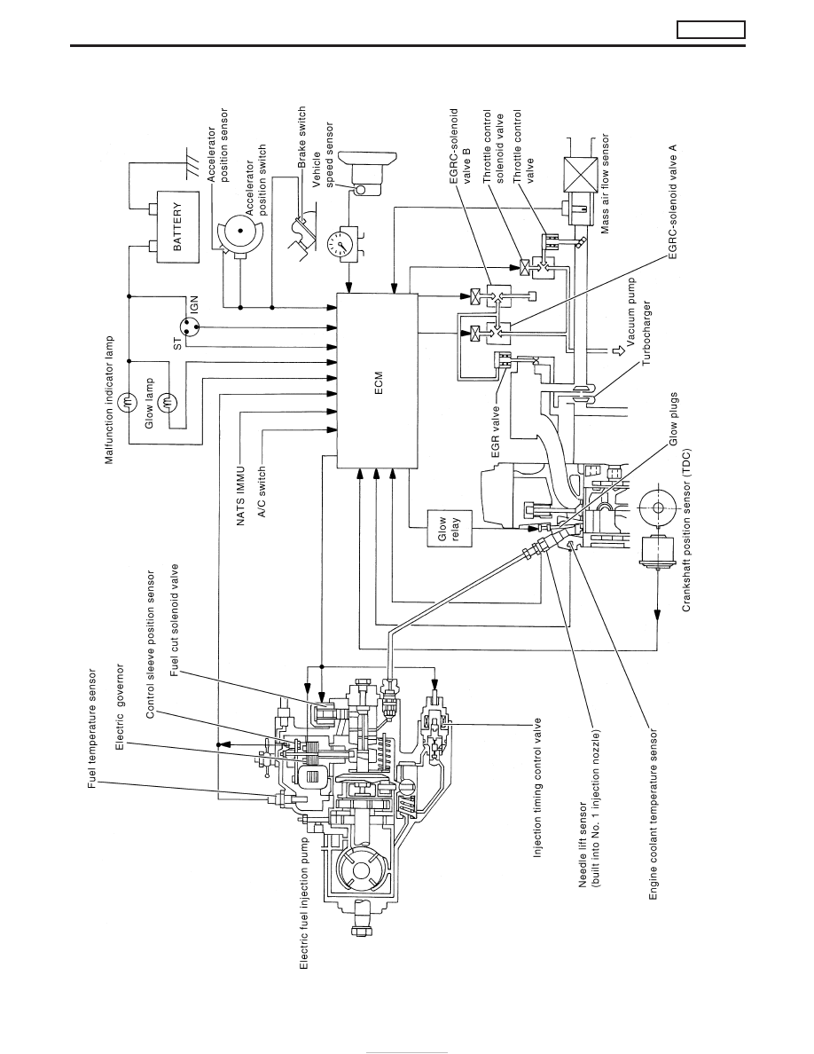
System Diagram
YEC695A
ENGINE AND EMISSION CONTROL OVERALL SYSTEM
TD27Ti
EC-326