Nissan Terrano model r20 series 2004. Manual - part 139


  Index      Nissan     Nissan Terrano model r20 series 2004 - Service and Repair Manual


Search            


Content   ..  137  138  139  140   ..


Nissan Terrano model r20 series 2004. Manual - part 139


6

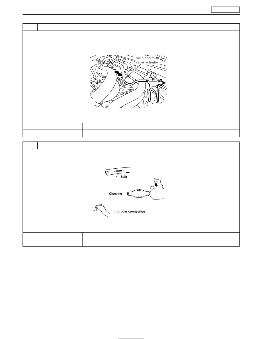
CHECK SWIRL CONTROL VALVE ACTUATOR

1. Turn ignition switch “OFF”.
2. Install a vacuum pump to swirl control valve actuator.
3. Make sure that the swirl control valve actuator rod moves smoothly when applying vacuum of −93.3 kPa (−933 mbar, −700
mmHg, −27.6 inHg) and releasing it.

MEC010E

OK or NG

OK

E

Repair or replace vacuum hoses and vacuum gallery.

NG

E

Replace swirl control valve actuator.

7

CHECK VACUUM HOSE

1. Turn ignition switch “OFF”.
2. Check vacuum hoses and vacuum gallery for clogging, cracks or improper connection.

SEF109L

OK or NG

OK

E

GO TO 8.

NG

E

Repair or replace vacuum hoses and vacuum gallery.

SWIRL CONTROL VALVE CONTROL SOLENOID VALVE

ZD30DDTi

Diagnostic Procedure (Cont’d)

EC-278

8

CHECK SWIRL CONTROL VALVE CONTROL SOLENOID VALVE POWER SUPPLY CIRCUIT

1. Turn ignition switch “OFF”.
2. Disconnect swirl control valve control solenoid valve harness connector.

MEC006E

3. Turn ignition switch “ON”.
4. Check voltage between swirl control valve control solenoid valve terminal 2 and ground with CONSULT-II or tester.

SEF312Z

OK or NG

OK

E

GO TO 10.

NG

E

GO TO 9.

9

DETECT MALFUNCTIONING PART

Check the following.

I

Harness connectors F108, E225

I

Harness connectors M842, F135

I

Fuse block (J/B) connector F48 (LHD models), M756 (RHD models)

I

10A fuse

I

Harness for open or short between swirl control valve control solenoid valve and fuse

E

Repair open circuit or short to ground or short to power in harness or connectors.

10

CHECK SWIRL CONTROL VALVE CONTROL SOLENOID VALVE OUTPUT SIGNAL CIRCUIT FOR OPEN OR SHORT

1. Turn ignition switch “OFF”.
2. Disconnect ECM harness connector.
3. Check harness continuity between ECM terminal 54 and swirl control valve control solenoid valve terminal 1. Refer to Wiring

Diagram.

Continuity should exist.

4. Also check harness for short to ground and short to power.

OK or NG

OK

E

GO TO 12.

NG

E

GO TO 11.

SWIRL CONTROL VALVE CONTROL SOLENOID VALVE

ZD30DDTi

Diagnostic Procedure (Cont’d)

EC-279

11

DETECT MALFUNCTIONING PART

Check the following.

I

Harness connectors E227, F106

I

Harness connectors F135, M842 (RHD models)

I

Harness for open or short between swirl control valve control solenoid valve and ECM

E

Repair open circuit or short to ground or short to power in harness or connectors.

12

CHECK SWIRL CONTROL VALVE CONTROL SOLENOID VALVE

With CONSULT-II

1. Reconnect all disconnected harness connectors.
2. Turn ignition switch “ON”.
3. Select “SWIRL CONT S/V 1” in “ACTIVE TEST” mode with CONSULT-II.
4. Check air passage continuity of swirl control valve control solenoid valve under the following conditions.

SEF313Z

Without CONSULT-II

1. Apply 12V direct current between swirl control valve control solenoid valve terminals.
2. Check air passage continuity of swirl control valve control solenoid valve under the following conditions.

SEF335X

OK or NG

OK

E

GO TO 13.

NG

E

Replace swirl control valve control solenoid valve.

13

CHECK INTERMITTENT INCIDENT

Perform “TROUBLE DIAGNOSIS FOR INTERMITTENT INCIDENT”, EC-78.

E

INSPECTION END

SWIRL CONTROL VALVE CONTROL SOLENOID VALVE

ZD30DDTi

Diagnostic Procedure (Cont’d)

EC-280

Description

Vibration when stopping the engine can be controlled by cutting
intake air just before the fuel is cut. The intake air control valve
control solenoid valve controls the ON-OFF load of the intake air
control valve actuator. As a result, the intake air control valve con-
trol solenoid valve will be turned ON when the ignition switch is
turned OFF with the engine running and when the engine stalls.
After the engine has stopped, the intake air control valve control
solenoid valve will return to fully open.

Operation

Sensor

Input Signal to ECM

ECM

Function

Actuator

Ignition switch

OFF

Intake

air con-

trol

valve

control

Intake air control valve control solenoid

valve

"

Intake air control valve actuator

Crankshaft position sensor (TDC)

Engine stall

ECM Terminals and Reference Value

Specification data are reference values, and are measured between each terminal and ground.

CAUTION:

Do not use ECM ground terminals when measuring input/output voltage. Doing so may damage the
ECM’s transistor. Use a ground other than ECM terminals, such as the ground.

TER-

MINAL

NO.

WIRE

COLOR

ITEM

CONDITION

DATA (DC Voltage)

2

LG

Intake air control valve
control solenoid valve

Engine is running.

BATTERY VOLTAGE
(11 - 14V)

Ignition switch “OFF”

For a few seconds after engine stops

Approximately 0.1V

MEC006E

INTAKE AIR CONTROL VALVE CONTROL SOLENOID

VALVE

ZD30DDTi

EC-281


Content   ..  137  138  139  140   ..