Nissan Terrano model r20 series 2004. Manual - part 123
ECM Terminals and Reference Value
Specification data are reference values and are measured between each terminal and ground.
CAUTION:
Do not use ECM ground terminals when measuring input/output voltage. Doing so may damage the
ECM’s transistor. Use a ground other than ECM terminals, such as the ground.
TER-
MINAL
NO.
WIRE
COLOR
ITEM
CONDITION
DATA (DC Voltage)
4
G
ECM relay (Self-shutoff)
Ignition switch “ON”
Ignition switch “OFF”
For a few seconds after turning ignition switch
“OFF”
Approximately 0.25V
Ignition switch “OFF”
More than a few seconds after turning ignition
switch “OFF”
BATTERY VOLTAGE
(11 - 14V)
38
B/W
Ignition switch
Ignition switch “OFF”
0V
Ignition switch “ON”
BATTERY VOLTAGE
(11 - 14V)
56
61
116
B/W
B/W
B/W
Power supply for ECM
Ignition switch “ON”
BATTERY VOLTAGE
(11 - 14V)
On Board Diagnosis Logic
Malfunction is detected when ....
Check Items (Possible Cause)
I
An irregular voltage signal from the ECM relay is sent to ECM.
I
Harness or connectors
(ECM relay circuit is open or shorted.)
I
ECM relay
DTC Confirmation Procedure
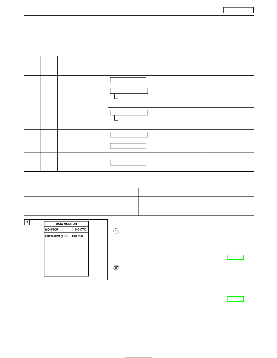
WITH CONSULT-II
1) Turn ignition switch “ON”.
2) Select “DATA MONITOR” mode with CONSULT-II.
3) Turn ignition switch “OFF”, wait at least 20 seconds and then
turn “ON”.
4) If DTC is detected, go to “Diagnostic Procedure”, EC-216.
WITHOUT CONSULT-II
1) Turn ignition switch “ON”.
2) Turn ignition switch “OFF”, wait at least 20 seconds and then
turn “ON”.
3) Perform “Diagnostic Test Mode II (Self-diagnostic results)” with
ECM.
4) If DTC is detected, go to “Diagnostic Procedure”, EC-216.
SEF817Y
DTC 0902 ECM RLY
ZD30DDTi
EC-214