Nissan Terrano model r20 series 2004. Manual - part 91
14
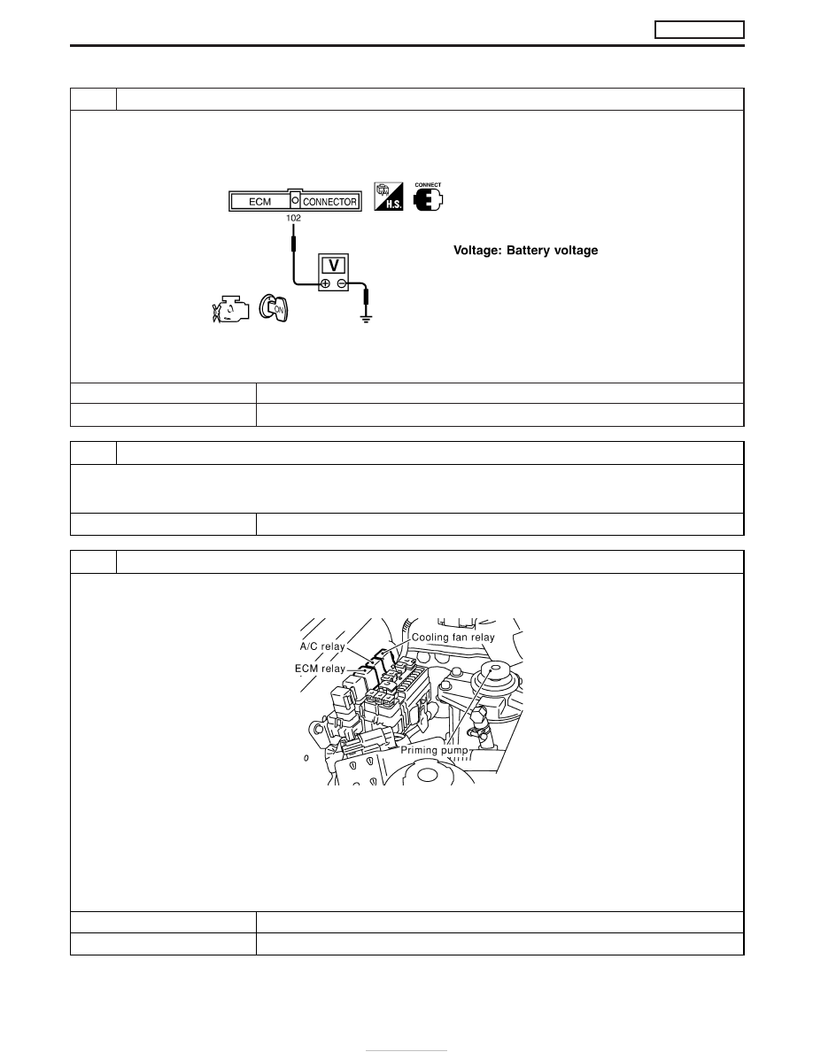
CHECK ECM POWER SUPPLY CIRCUIT-V
1. Reconnect all harness connectors disconnected.
2. Turn ignition switch “ON”.
3. Check voltage between ECM terminal 102 and ground with CONSULT-II or tester.
SEF290Z
OK or NG
OK
E
GO TO 16.
NG
E
GO TO 15.
15
DETECT MALFUNCTIONING PART
Check the following.
I
10A fuse
I
Harness for open or short between ECM and fuse
E
Repair open circuit or short to ground or short to power in harness or connectors.
16
CHECK ECM POWER SUPPLY CIRCUIT-VI
1. Turn ignition switch “OFF”.
2. Disconnect ECM relay.
MEC021E
3. Disconnect ECM harness connector.
4. Check harness continuity between ECM terminals 56, 61, 116 and ECM relay terminal 5. Refer to Wiring Diagram.
Continuity should exist.
5. Also check harness for short to ground and short to power.
OK or NG
OK
E
GO TO 18.
NG
E
GO TO 17.
TROUBLE DIAGNOSIS FOR POWER SUPPLY
ZD30DDTi
Main Power Supply and Ground Circuit
(Cont’d)
EC-86