Nissan Terrano model r20 series 2004. Manual - part 90
 

  Index      Nissan     Nissan Terrano model r20 series 2004 - Service and Repair Manual


Search            


Content   ..  88  89  90  91   ..


Nissan Terrano model r20 series 2004. Manual - part 90


DIAGNOSTIC PROCEDURE

1

INSPECTION START

Start engine.
Is engine running?

Yes or No

Yes

E

GO TO 14.

No

E

GO TO 2.

2

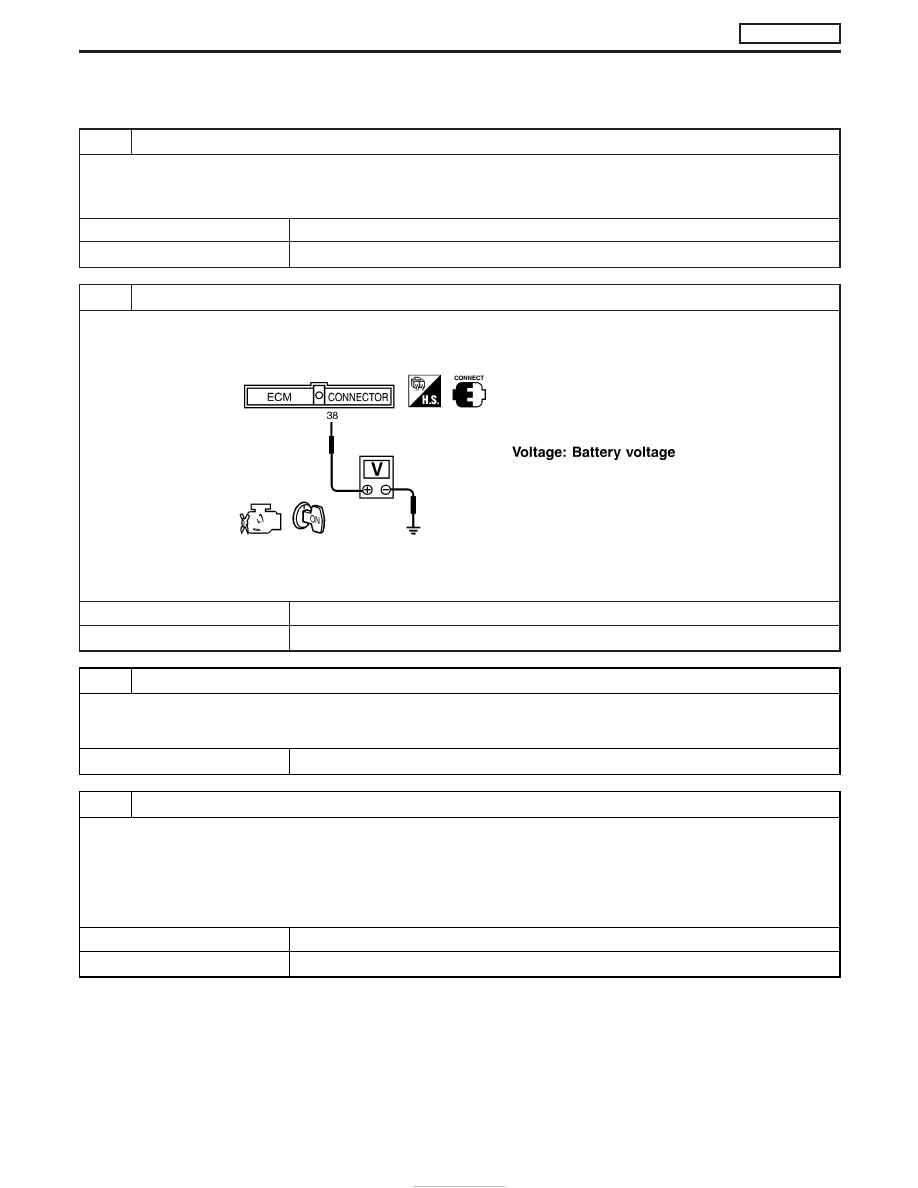
CHECK ECM POWER SUPPLY CIRCUIT-I

1. Turn ignition switch “ON”.
2. Check voltage between ECM terminal 38 and ground with CONSULT-II or tester.

SEF397Y

OK or NG

OK

E

GO TO 4.

NG

E

GO TO 3.

3

DETECT MALFUNCTIONING PART

Check the following.

I

10A fuse

I

Harness for open or short between ECM and fuse

E

Repair open circuit or short to ground or short to power in harness or connectors.

4

CHECK ECM GROUND CIRCUIT FOR OPEN AND SHORT

1. Turn ignition switch “OFF”.
2. Disconnect ECM harness connector.
3. Check harness continuity between ECM terminals 39, 43, 106, 112, 118 and engine ground. Refer to Wiring Diagram.

Continuity should exist.

4. Also check harness for short to ground and short to power.

OK or NG

OK

E

GO TO 6.

NG

E

GO TO 5.

TROUBLE DIAGNOSIS FOR POWER SUPPLY

ZD30DDTi

Main Power Supply and Ground Circuit
(Cont’d)

EC-82

5

DETECT MALFUNCTIONING PART

Check the following.

I

Harness connectors F108, E225

I

Harness connectors M842, F135 (RHD models)

I

Harness for open or short between ECM and engine ground

E

Repair open circuit or short to ground or short to power in harness or connectors.

6

CHECK ECM POWER SUPPLY CIRCUIT-II

1. Reconnect ECM harness connector.
2. Turn ignition switch “ON” and then “OFF”.
3. Check voltage between ECM terminals 56, 61, 116 and ground with CONSULT-II or tester.

SEF288Z

OK or NG

OK

E

Check electronic control fuel injection pump power supply circuit. Refer to “Diagnostic
Procedure”, EC-185.

NG (Battery voltage does not
exist.)

E

GO TO 7.

NG (Battery voltage exists for
more than a few seconds.)

E

GO TO 13.

TROUBLE DIAGNOSIS FOR POWER SUPPLY

ZD30DDTi

Main Power Supply and Ground Circuit
(Cont’d)

EC-83

7

CHECK ECM POWER SUPPLY CIRCUIT-III

1. Disconnect ECM relay.

MEC021E

2. Check voltage between relay terminals 2, 3 and ground with CONSULT-II or tester.

MEC978D

Voltage: Battery Voltage

OK or NG

OK

E

GO TO 9.

NG

E

GO TO 8.

8

DETECT MALFUNCTIONING PART

Check the following.

I

10A fuse

I

15A fuse

I

Harness for open or short between ECM relay and battery

E

Repair open circuit or short to ground or short to power in harness or connectors.

9

CHECK OUTPUT SIGNAL CIRCUIT FOR OPEN AND SHORT

1. Disconnect ECM harness connector.
2. Check harness continuity between ECM terminal 4 and ECM relay terminal 1. Refer to Wiring Diagram.

Continuity should exist.

3. Also check harness for short to ground and short to power.

OK or NG

OK

E

GO TO 11.

NG

E

GO TO 10.

TROUBLE DIAGNOSIS FOR POWER SUPPLY

ZD30DDTi

Main Power Supply and Ground Circuit
(Cont’d)

EC-84

10

DETECT MALFUNCTIONING PART

Check the following.

I

Harness connectors M787, F66 (LHD models)

I

Harness for open or short between ECM and ECM relay

E

Repair open circuit or short to ground or short to power in harness or connectors.

11

CHECK ECM POWER SUPPLY CIRCUIT-IV

1. Check harness continuity between ECM terminals 56, 61, 116 and ECM relay terminal 5. Refer to Wiring Diagram.

Continuity should exist.

2. Also check harness for short to ground and short to power.

OK or NG

OK

E

GO TO 13.

NG

E

GO TO 12.

12

DETECT MALFUNCTIONING PART

Check the following.

I

Harness connectors M787, F66 (LHD models)

I

Harness for open or short between ECM and ECM relay

E

Repair open circuit or short to ground or short to power in harness or connectors.

13

CHECK ECM RELAY

1. Apply 12V direct current between ECM relay terminals 1 and 2.
2. Check continuity between ECM relay terminals 3 and 5, 6 and 7.

SEF296X

OK or NG

OK

E

GO TO 14.

NG

E

Replace ECM relay.

TROUBLE DIAGNOSIS FOR POWER SUPPLY

ZD30DDTi

Main Power Supply and Ground Circuit
(Cont’d)

EC-85


Content   ..  88  89  90  91   ..