Nissan Terrano model r20 series 2004. Manual - part 89
Description
Intermittent incidents (I/I) may occur. In many cases, the problem resolves itself (the part or circuit function
returns to normal without intervention). It is important to realize that the symptoms described in the custom-
er’s complaint often do not recur on DTC visits. Realize also that the most frequent cause of I/I occurrences
is poor electrical connections. Because of this, the conditions under which the incident occurred may not be
clear. Therefore, circuit checks made as part of the standard diagnostic procedure may not indicate the spe-
cific problem area.
COMMON I/I REPORT SITUATIONS
STEP in Work Flow
Situation
II
The CONSULT-II is used. The SELF-DIAG RESULTS screen shows time data other than “0”.
III
The symptom described by the customer does not recur.
IV
DTC does not appear during the DTC Confirmation Procedure.
VI
The Diagnostic Procedure for XXXX does not indicate the problem area.
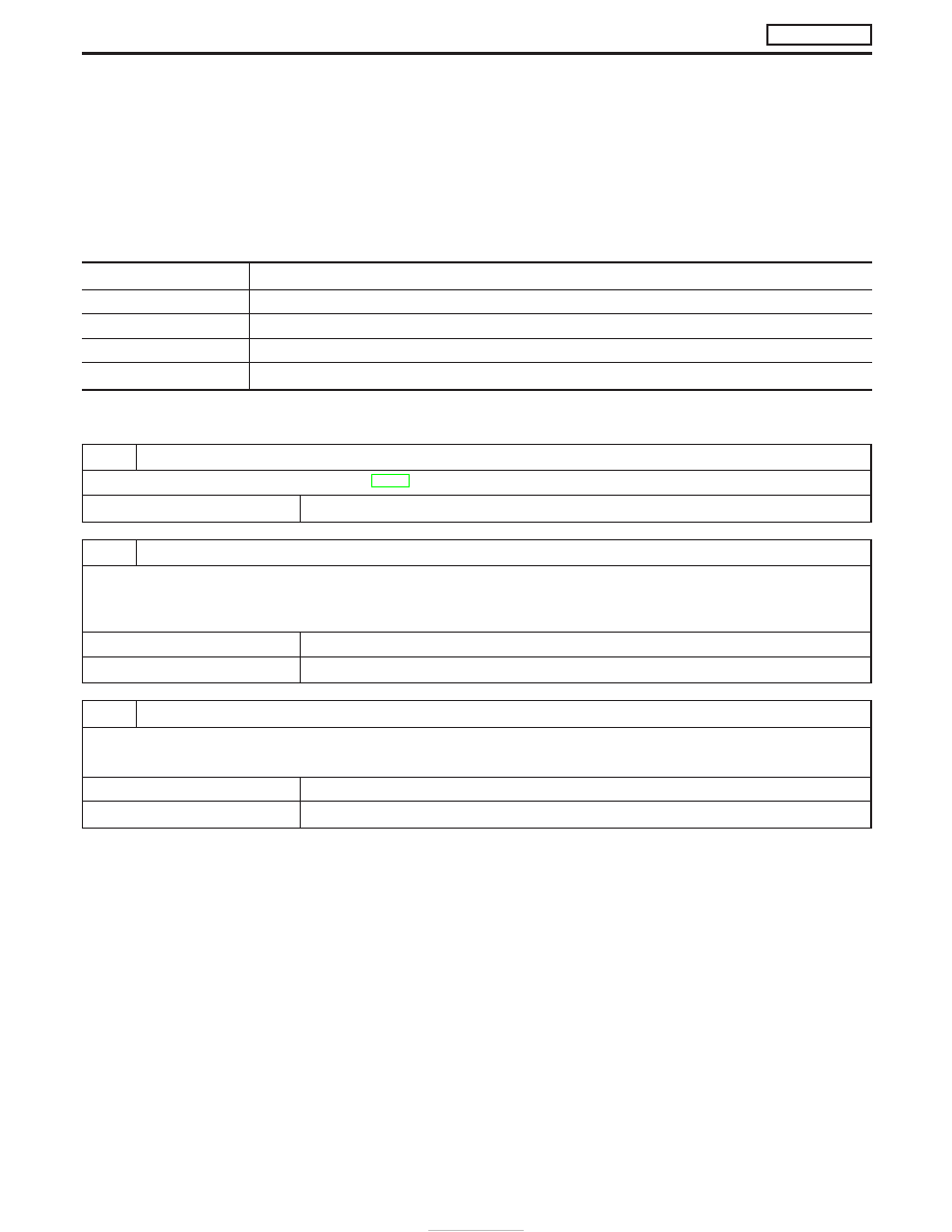
Diagnostic Procedure
1
INSPECTION START
Erase DTCs. Refer to “HOW TO ERASE DTC”, EC-33.
E
GO TO 2.
2
CHECK GROUND TERMINALS
Check ground terminals for corroding or loose connection.
Refer to GI section (“GROUND INSPECTION”, “Circuit Inspection”).
OK or NG
OK
E
GO TO 3.
NG
E
Repair or replace.
3
SEARCH FOR ELECTRICAL INCIDENT
Perform GI section, “Incident Simulation Tests”.
OK or NG
OK
E
INSPECTION END
NG
E
Repair or replace.
TROUBLE DIAGNOSIS FOR INTERMITTENT INCIDENT
ZD30DDTi
EC-78