Nissan Terrano model r20 series 2004. Manual - part 87


  Index      Nissan     Nissan Terrano model r20 series 2004 - Service and Repair Manual


Search            


Content   ..  85  86  87  88   ..


Nissan Terrano model r20 series 2004. Manual - part 87


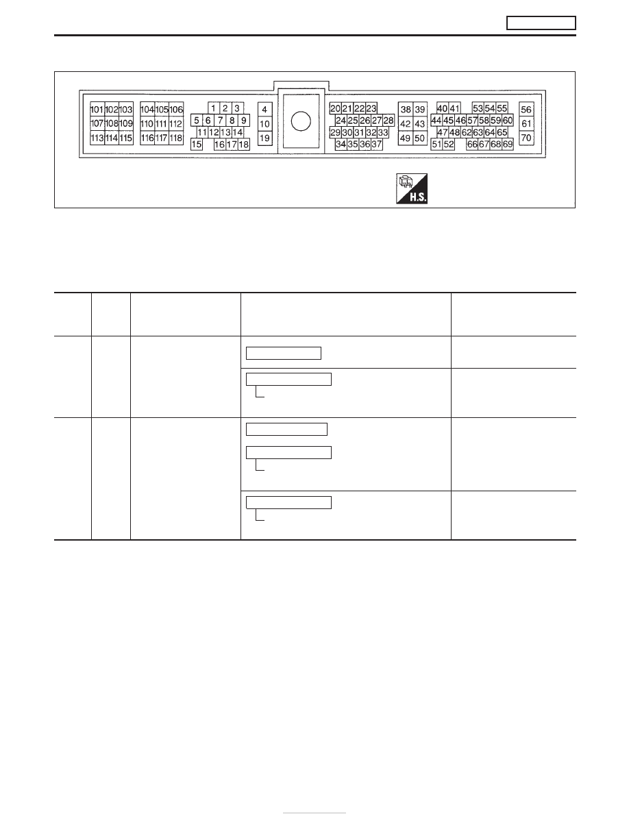
ECM HARNESS CONNECTOR TERMINAL LAYOUT

ECM INSPECTION TABLE

Remarks: Specification data are reference values and are measured between each terminal and ground.

CAUTION:

Do not use ECM ground terminals when measuring input/output voltage. Doing so may damage the
ECM’s transistor. Use a ground other than ECM terminals, such as the ground.

TER-

MINAL

NO.

WIRE

COLOR

ITEM

CONDITION

DATA (DC Voltage and Pulse

Signal)

2

LG

Intake air control valve
control solenoid valve

Engine is running.

BATTERY VOLTAGE
(11 - 14V)

Ignition switch “OFF”

For a few seconds after turning ignition
switch “OFF”

Approximately 0.1V

4

G

ECM relay (Self-shutoff)

Ignition switch “ON”

Ignition switch “OFF”

For a few seconds after turning ignition
switch “OFF”

Approximately 0.25V

Ignition switch “OFF”

More than a few seconds after turning igni-
tion switch “OFF”

BATTERY VOLTAGE
(11 - 14V)

SEF064P

TROUBLE DIAGNOSIS — GENERAL DESCRIPTION

ZD30DDTi

ECM Terminals and Reference Value (Cont’d)

EC-70

TER-

MINAL

NO.

WIRE

COLOR

ITEM

CONDITION

DATA (DC Voltage and Pulse

Signal)

5

L/B

Tachometer

Engine is running.

Warm-up condition
Idle speed

Approximately 5.7V

SEF255Z

Engine is running.

Warm-up condition
Engine speed is 2,000 rpm

Approximately 6V

SEF256Z

6

Y

Engine oil lamp

Ignition switch “ON”

Approximately 0V

Engine is running.

BATTERY VOLTAGE (11 -
14V)

14

LG/R

Cooling fan relay

Engine is running.

Cooling fan is not operating

BATTERY VOLTAGE
(11 - 14V)

Engine is running.

Cooling fan is operating

Approximately 0.1V

15

G/PU

Air conditioner relay

Engine is running.

Air conditioner switch is “OFF”

BATTERY VOLTAGE
(11 - 14V)

Engine is running.

Both air conditioner switch and blower fan
switch are “ON”
(Compressor is operating)

Approximately 0.1V

16

G/W

Glow lamp

Ignition switch “ON”

Glow lamp is “ON”

Approximately 1V

Ignition switch “ON”

Glow lamp is “OFF”

BATTERY VOLTAGE
(11 - 14V)

TROUBLE DIAGNOSIS — GENERAL DESCRIPTION

ZD30DDTi

ECM Terminals and Reference Value (Cont’d)

EC-71

TER-

MINAL

NO.

WIRE

COLOR

ITEM

CONDITION

DATA (DC Voltage and Pulse

Signal)

17

G/Y

Stop lamp switch

Ignition switch “ON”

Brake pedal fully released

Approximately 0V

Ignition switch “ON”

Brake pedal depressed

BATTERY VOLTAGE
(11 - 14V)

18

L

Malfunction indicator

Ignition switch “ON”

Approximately 1V

Engine is running.

Idle speed

BATTERY VOLTAGE
(11 - 14V)

19

LG/W

Engine coolant tempera-
ture sensor

Engine is running.

Approximately 0 - 4.8V
Output voltage varies with
engine coolant temperature

20

PU

Start signal

Ignition switch “ON”

Approximately 0V

Ignition switch “START”

BATTERY VOLTAGE
(11 - 14V)

21

G/R

Air conditioner switch

Engine is running.

Air conditioner switch is “OFF”

BATTERY VOLTAGE
(11 - 14V)

Engine is running.

Both air conditioner switch and blower fan
switch are “ON”
(Compressor is operating)

Approximately 0.1V

22

BR/Y
(A/T)
G
(M/T)

Park/Neutral position
switch

Ignition switch “ON”

Gear position is “Neutral” (M/T models)
Gear position is “P” or “N” (A/T models)

Approximately 0V

Ignition switch “ON”

Except the above gear position

BATTERY VOLTAGE
(11 - 14V)

23

G

Accelerator position sen-
sor

Ignition switch “ON”

Accelerator pedal fully released

0.4 - 0.6V

Ignition switch “ON”

Accelerator pedal fully depressed

Approximately 4.5V

24

G/Y

A/T signal No. 1

Engine is running.

Warm-up condition
Idle speed

Voltage goes high up once in
a few seconds

SEF448Z

TROUBLE DIAGNOSIS — GENERAL DESCRIPTION

ZD30DDTi

ECM Terminals and Reference Value (Cont’d)

EC-72

TER-

MINAL

NO.

WIRE

COLOR

ITEM

CONDITION

DATA (DC Voltage and Pulse

Signal)

26

Y/B

Vehicle speed sensor

Engine is running.

Lift up the vehicle
In 1st gear position
Vehicle speed is 10 km/h (6 MPH)

0 - Approximately 4.8V

SEF257Z

Engine is running.

Lift up the vehicle
In 2nd gear position
Vehicle speed is 30 km/h (19 MPH)

Approximately 2.2V

SEF258Z

27

R/L

Engine oil pressure
switch-2

Ignition switch “ON”

Approximately 0V

Engine is running.

BATTERY VOLTAGE (11 -
14V)

29

LG/R

Accelerator switch (F/C)

Ignition switch “ON”

Accelerator pedal fully released

BATTERY VOLTAGE
(11 - 14V)

Ignition switch “ON”

Accelerator pedal depressed

Approximately 0V

30

LG/Y

A/T signal No. 3

Engine is running.

Warm-up condition
Idle speed

Approximately 0V

Engine is running.

Warm-up condition
Engine speed is 2,000 rpm

Approximately 7.7V

31

L/Y

Accelerator position
switch (Idle)

Ignition switch “ON”

Accelerator pedal fully released

BATTERY VOLTAGE
(11 - 14V)

Ignition switch “ON”

Accelerator pedal depressed

Approximately 0V

32

R/L

Accelerator position
switch (Full)

Ignition switch “ON”

Accelerator pedal released

Approximately 0V

Ignition switch “ON”

Accelerator pedal fully depressed

BATTERY VOLTAGE
(11 - 14V)

33

G

Electronic control fuel
injection pump

Engine is running.

Warm-up condition
Idle speed

Approximately 2.5V

TROUBLE DIAGNOSIS — GENERAL DESCRIPTION

ZD30DDTi

ECM Terminals and Reference Value (Cont’d)

EC-73


Content   ..  85  86  87  88   ..