Nissan Terrano model r20 series 2004. Manual - part 77


  Index      Nissan     Nissan Terrano model r20 series 2004 - Service and Repair Manual


Search            


Content   ..  75  76  77  78   ..


Nissan Terrano model r20 series 2004. Manual - part 77


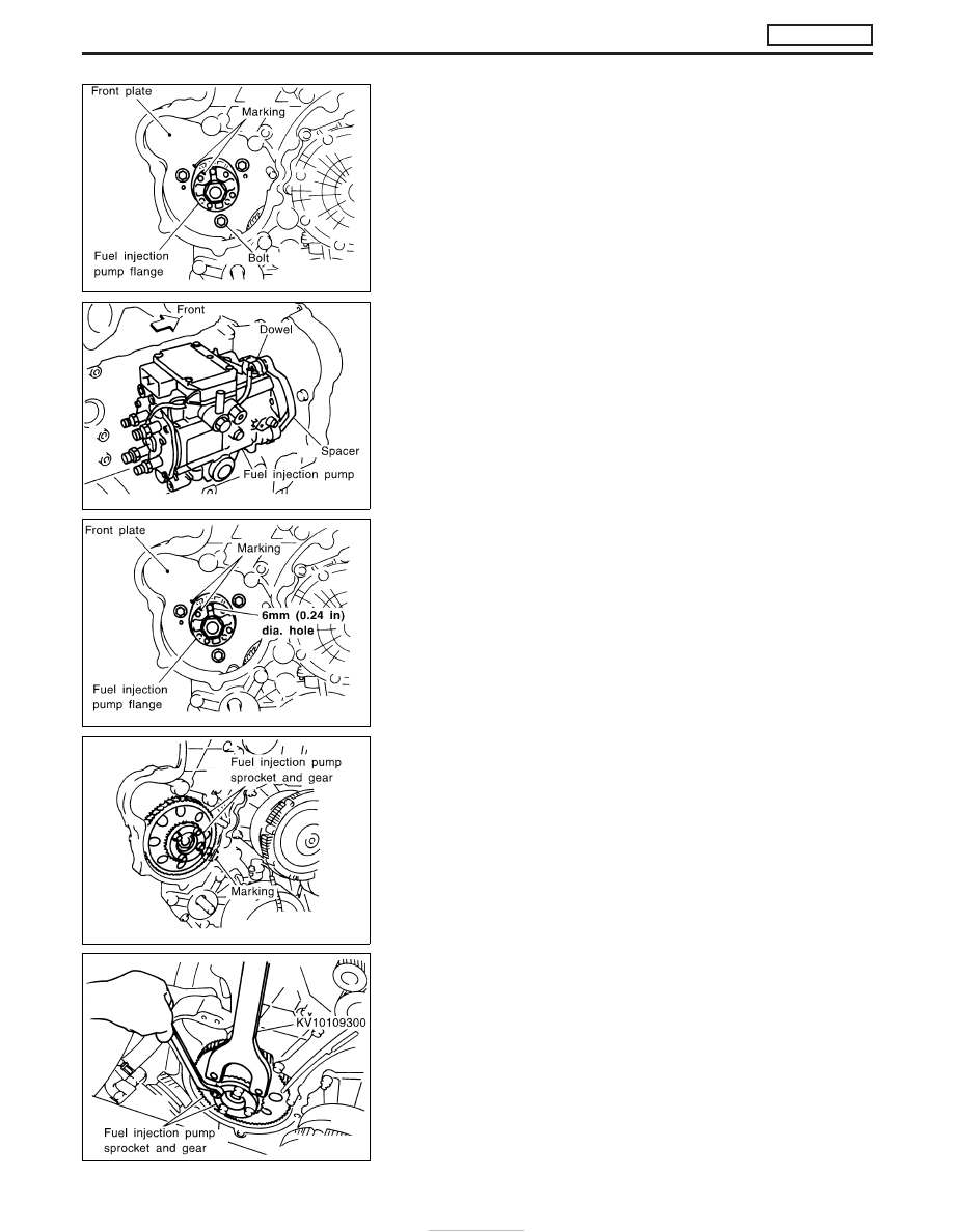
13. Make the mating marks on the fuel injection pump flange and

front plate with paint.

14. Remove installation bolts first, and then fuel injection pump

toward the rear side of the engine.

I

When the fuel injection pump is stationary, it can still be
retained by the dowel without all bolts.

CAUTION:

Do not disassemble or adjust the fuel injection pump.

INSTALLATION

I

The injection timing adjustment to correct the installation angle
deviation is not necessary. Install the pump in the proper posi-
tion according to the dowel and installation bolts.

1. Install the fuel injection pump from the rear side of the engine.

I

Match the dowel of the spacer to the dowel hole of the pump
side for installation.

I

Replace the seal washer of the installation bolt with a new one.

2. Align the mating marks of the fuel injection pump flange and

front plate, and then adjust the approximate flange position.

I

Each hole [6 mm (0.24 in) dia.] is used as a reference point for
the fuel injection pump flange, fuel injection pump gear, and fuel
injection pump sprocket.

I

Only during removal/installation at No. 1 cylinder compression
top dead center, can the hole [6 mm (0.24 in) dia.] of the pump
body be aligned.

3. Install the fuel injection pump sprocket and gear as an assem-

bly.

I

Align the mating marks of the idler gear and fuel injection pump
gear properly.

4. Tighten the installation bolt of the fuel injection pump sprocket.

I

Fix the fuel injection pump gear with the pulley holder (SST),
and tighten the installation bolt.

CAUTION:

Before tightening the installation bolt, check again that the
mating marks of the idler gear and fuel injection pump gear are
aligned.

JEF268Z

JEF269Z

JEF270Z

JEF271Z

JEF267Z

BASIC SERVICE PROCEDURE

ZD30DDTi

Electronic Control Fuel Injection Pump (Cont’d)

EC-30

5. Install the cam sprocket and timing chain at the same time.

I

Align the mating marks of the fuel injection pump sprocket and
cam sprocket, and install the timing chain.

I

Holding the hexagon head of the camshaft with a wrench,
tighten the cam sprocket installation bolt.

CAUTION:

Do not tighten the installation bolt using a chain tension.
6. Install the timing chain, related parts, and the chain cover.

Refer to EM section, “TIMING CHAIN”.

7. Remove the tightening bolt of the idler gear internal mecha-

nism.

8. Apply the liquid gasket to the screw of the plug, and tighten the

plug.

: 7.9 - 9.8 N

m (0.8 - 1.0 kg-m, 70 - 86 in-lb)

I

Use Genuine Liquid Gasket or equivalent.

9. Install the fuel injection pump rear bracket.

I

Tighten all the installation bolts temporarily, and then tighten
them firmly with both surfaces of the fuel injection pump and
cylinder block attached to the installation surface.

10. Connect the harness connector of the fuel injection pump.

I

Insert the harness connector until the stopper is completely
locked.

I

When the connector is pushed fully to lock the stopper, the
interlocked-connector is inserted.

11. Installation is in the reverse order of removal.

JEF264Z

JEF272Z

JEF273Z

JEF260Z

BASIC SERVICE PROCEDURE

ZD30DDTi

Electronic Control Fuel Injection Pump (Cont’d)

EC-31

Air Bleeding

Pump the priming pump to bleed air.

I

When air is bled completely, the pumping of the priming
pump suddenly becomes heavy. Stop operation at that
time.

I

If it is difficult to bleed air by the pumping of the priming
pump (the pumping of the priming pump does not become
heavy), disconnect the fuel supply hose between the fuel
filter and the injection pump. Then, perform the operation
described above, and make sure that fuel comes out. (Use
a pan, etc. so as not to spill fuel. Do not let fuel get on
engine and other parts.) After that, connect the hose, and
then bleed air again.

MEC991D

BASIC SERVICE PROCEDURE

ZD30DDTi

EC-32

DTC and MI Detection Logic

When a malfunction is detected, the malfunction (DTC) is stored in the ECM memory.
The MI will light up each time the ECM detects malfunction. For diagnostic items causing the MI to light up,
refer to “TROUBLE DIAGNOSIS — INDEX”, EC-7.

Diagnostic Trouble Code (DTC)

HOW TO READ DTC

The DTC can be read by the following methods.

Without CONSULT-II

ECM displays the DTC by a set of four digit numbers with MI illumination in the diagnostic test mode II (Self-
diagnostic results). Example: 0102, 0407, 1004, etc.

With CONSULT-II

CONSULT-II displays the DTC in “SELF-DIAG RESULTS” mode. Examples: “CRANK POS SEN (TDC)”, etc.

I

Output of the trouble code means that the indicated circuit has a malfunction. However, in the Mode
II it does not indicate whether the malfunction is still occurring or occurred in the past and returned
to normal.
CONSULT-II can identify them. Therefore, using CONSULT-II (if available) is recommended.

HOW TO ERASE DTC

How to erase DTC (

With CONSULT-II)

1. If the ignition switch stays “ON” after repair work, be sure to turn ignition switch “OFF” once. Wait at least

5 seconds and then turn it “ON” (engine stopped) again.

2. Touch “ENGINE”.
3. Touch “SELF-DIAG RESULTS”.
4. Touch “ERASE”. (The DTC in the ECM will be erased.)

The emission related diagnostic information in the ECM can be erased by selecting “ERASE” in the “SELF-
DIAG RESULTS” mode with CONSULT-II.

How to erase DTC (

Without CONSULT-II)

1. If the ignition switch stays “ON” after repair work, be sure to turn ignition switch “OFF” once. Wait at least

5 seconds and then turn it “ON” (engine stopped) again.

2. Change the diagnostic test mode from Mode II to Mode I by using the data link connector. (See EC-36.)
The emission related diagnostic information in the ECM can be erased by changing the diagnostic test mode.

SEF371Y

ON BOARD DIAGNOSTIC SYSTEM DESCRIPTION

ZD30DDTi

EC-33


Content   ..  75  76  77  78   ..