Nissan Terrano model r20 series 2004. Manual - part 76


  Index      Nissan     Nissan Terrano model r20 series 2004 - Service and Repair Manual


Search            


Content   ..  74  75  76  77   ..


Nissan Terrano model r20 series 2004. Manual - part 76


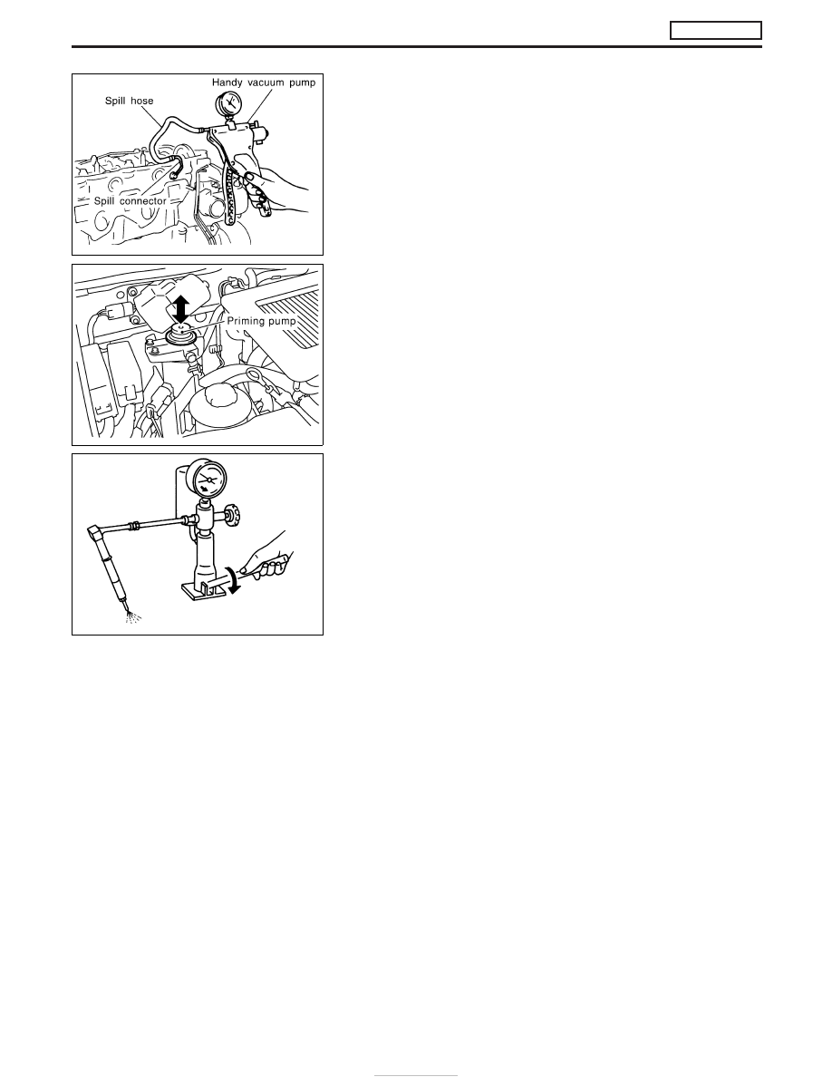
Inspection for spill tube airtightness

Before the rocker cover is installed, perform the inspection as fol-
lows.
1. Connect the handy vacuum pump to the spill hose.
2. Check that the airtightness is maintained after the negative

pressure shown below is applied.

Standard:

−53.3 to −66.7 kPa (−533 to −667 mbar, −400 to
−500 mmHg, −15.75 to −19.69 inHg)

Air bleeding of fuel piping

After the repair, bleed air in the piping by pumping the priming
pump up and down until it becomes heavy.

Injection pressure test

1. Install injection nozzle assembly to injection nozzle tester and

bleed air from flare nut.

2. Pump the tester handle slowly (one time per second) and watch

the pressure gauge.

3. Read the pressure gauge when the injection pressure just

starts dropping.

Initial injection pressure:

Used

19,026 kPa (190.3 bar, 194 kg/cm

2

, 2,759 psi)

New

19,516 - 20,497 kPa (195.2 - 205.0 bar, 199 - 209
kg/cm

2

, 2,830 - 2,972 psi)

Limit

16,182 kPa (161.8 bar, 165 kg/cm

2

, 2,346 psi)

I

The injection nozzle assembly has a 2-stage pressure injection
function. However, the judgement should be made at the first
stage of the valve opening pressure.

JEF250Z

MEC991D

JEF348Y

BASIC SERVICE PROCEDURE

ZD30DDTi

Injection Tube and Injection Nozzle (Cont’d)

EC-26

Spray pattern test

1. Check spray pattern by pumping tester handle one full stroke

per second.

NG spray pattern:

Does not inject straight and strong (B in the fig-
ure).
Fuel drips (C in the figure).
Does not inject evenly (D in the figure).

2. If the spray pattern is not correct, replace injection nozzle

assembly.

Electronic Control Fuel Injection Pump

REMOVAL AND INSTALLATION

CAUTION:

When removing or installing the timing chain as incidental work of the fuel injection pump removal/
installation, always secure the internal mechanism of the idler gear with bolts before removing or
installing the fuel injection pump sprocket. Do not refer to the procedure for “TIMING CHAIN” in EM
section based on No. 1 cylinder compression top dead center. (Unless otherwise specified.)

JEF349Y

JEF259Z

BASIC SERVICE PROCEDURE

ZD30DDTi

Injection Tube and Injection Nozzle (Cont’d)

EC-27

REMOVAL

1. Remove the following:

I

Engine coolant draining

I

Charge air cooler

I

Air inlet pipe

I

Throttle body

I

Rocker cover

I

Oil level gauge guide

I

EGR cooler

I

EGR guide tube

I

EGR volume control solenoid valve

I

Fuel hose

I

Injection tube

I

Radiator upper hose

I

Radiator shroud

I

Cooling fan

I

Drive belt

I

Vacuum pipe

I

Vacuum pump

2. Move the power steering pump.

3. Remove the harness connector from the fuel injection pump.

I

After pulling the connector stopper all the way back, remove the
connector.

I

When the stopper is pulled all the way back, the interlocked-
connector will come off.
As for installation, when the connector is pushed all the way
forward until the stopper locks, the interlocked-connector is
inserted.

4. Remove the fuel injection pump rear bracket.

5. Remove the chain cover.

I

Remove the installation bolts A, B, and C shown in the figure
(left).

CAUTION:

During chain cover removal, seal the opening to prevent for-
eign objects from getting into the engine.

6. Fix the internal mechanism of the idler gear (scissors gear

structure).

a. Remove the plug on the front side of the gear case.
b. While turning the crankshaft pulley clockwise, check the tight-

ening bolt hole of the idler gear internal mechanism through the
plug hole.

I

Conduct the visual check using a mirror.

I

When checking, note that there are 2 other holes (with no
thread) beside the tightening bolt hole on the idler gear.

JEF260Z

JEF261Z

JEF262Z

BASIC SERVICE PROCEDURE

ZD30DDTi

Electronic Control Fuel Injection Pump (Cont’d)

EC-28

c. Install the tightening bolt [Part No.: 81-20620-28, thread diam-

eter: M6, under head: 20 mm (0.79 in), pitch: 1.0 mm (0.039 in)]
to the idler gear tightening bolt hole, and tighten to the speci-
fied torque:

: 2.5 - 3.4 N

m (0.25 - 0.35 kg-m, 22 - 30 in-lb)

CAUTION:

I

To protect the idler gear from damage, do not use the sub-
stitute part for the tightening bolt.

I

Hereafter, do not turn the crankshaft to avoid hitting tight-
ening bolt head against the gear case.

I

Do not remove the idler gear tightening bolt before instal-
lations of the timing chain and related parts are completed.

7. Make mating marks on the cam sprocket, fuel injection pump

sprocket, and timing chain with paint.

8. Make mating marks on the fuel injection pump gear and idler

gear with paint.

9. Remove the chain tensioner.
(1) Loosen the upper and lower installation bolts.
(2) While holding the chain tensioner by hand, remove the upper

installation bolt to release the spring tension.

(3) Remove the lower installation bolt first, and then the chain ten-

sioner.

I

Since the chain tensioner does not have a mechanism to pre-
vent the plunger pop-out, watch out for the fall of the plunger
and spring. (Return prevention mechanism is available.)

10. Remove the timing chain slack guide.
11. Remove the cam sprocket and timing chain at the same time.

I

Make mating marks on each sprocket and timing chain.

I

Hold the hexagon head of the camshaft on the exhaust mani-
fold side, and loosen the cam sprocket installation bolt.

CAUTION:

Do not loosen the installation bolt using a chain tension.

12. Remove the fuel injection pump sprocket and gear as an

assembly.

I

Fix the fuel injection pump gear with the pulley holder (SST),
and loosen the installation bolt for removal.

I

Try not to move the pump shaft when removing.

I

Connect the sprocket and gear with a dowel pin, and tighten
them together with the installation bolt.

JEF263Z

JEF264Z

JEF265Z

JEF266Z

JEF267Z

BASIC SERVICE PROCEDURE

ZD30DDTi

Electronic Control Fuel Injection Pump (Cont’d)

EC-29


Content   ..  74  75  76  77   ..