Nissan Terrano model r20 series 2004. Manual - part 37


  Index      Nissan     Nissan Terrano model r20 series 2004 - Service and Repair Manual


Search            


Content   ..  35  36  37  38   ..


Nissan Terrano model r20 series 2004. Manual - part 37


IDLER GEAR OIL CLEARANCE

I

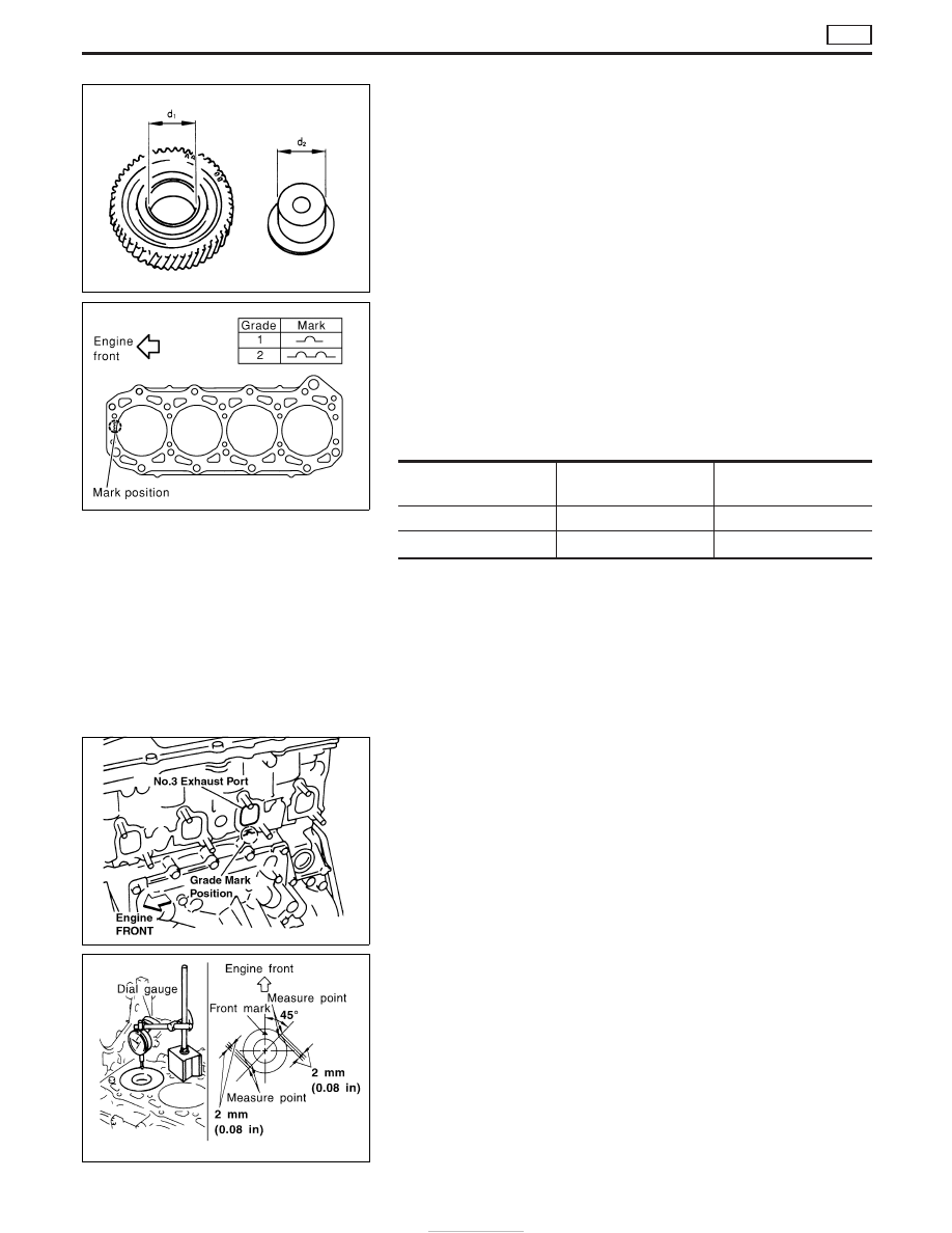
Measure the inner diameter (d

1

) of idler gear shaft hole.

Standard: 26.000 - 26.020 mm (1.0236 - 1.0244 in)

I

Measure the outer diameter (d

2

) of idler shaft.

Standard: 25.967 - 25.980 mm (1.0223 - 1.0228 in)

I

Calculate gear clearance.
Clearance = d

1

− d

2

Standard: 0.023 - 0.053 mm (0.0009 - 0.0021 in)

Installation

1. Install cylinder head gasket.

I

Cylinder head gasket to be installed is selected by its thickness
through the following procedure.

When replacing gasket only

I

Install gasket with same thickness as the one removed.

I

Gasket thickness is identified by the number of notches located
on rear-left side.

Grade

Gasket thickness*

mm (in)

No. of notches

1

0.65 (0.0256)

1

2

0.70 (0.0276)

2

*: Thickness of gasket tightened with head bolts

I

The number of notches can be checked at the position shown
in the figure before cylinder head is removed. (It is necessary
to remove exhaust manifold.)

When repairing/replacing the following

I

When the top of cylinder block or crankshaft pin/journal is
ground, or

I

When cylinder block, piston, connecting rod, or crankshaft is
replaced

1) Move piston toward TDC.
2) Position dial indicator on cylinder block as shown in the figure,

and adjust the needle to “0”.

3) Move dial indicator stand aside, and position the dial indicator

to the measuring point as shown in the figure.

4) Rotate crankshaft slowly, and read the value on dial indicator

at piston’s maximum height.

5) Repeat above procedure at 2 positions of each cylinder (8

positions in total for 4 cylinders), and select the appropriate
gasket by comparing the maximum crown depression with the
table.

FEM057

YEM031

FEM059

FEM060

CYLINDER HEAD

ZD

Inspection (Cont’d)

EM-54

Unit: mm (in)

Grade

Piston crown

depression

Gasket thick-

ness*1

No. of notches

1

Less than −0.078

(−0.0031)*2

0.65 (0.0256)

1

2

More than −0.078

(−0.0031)*3

0.70 (0.0276)

2

*1: Thickness of gasket tightened with head bolts
*2: Indicates values such as −0.080 mm (−0.0031 in).
*3: Indicates values such as −0.075 mm (−0.0030 in).

2. Install idler gear and idler shaft.

I

Check that the counter marks with cam gear, “AA” and “BB”, are
located on the front side of the engine.
Refer to EM-52.

CAUTION:

Since idler gear cannot be installed or removed with cylinder
head assembly mounted on the engine because of interfer-
ence with gear case, make sure that there are no reverse
installations or uninstalled parts.

3. Install cylinder head assembly.
1) Attach gasket onto the rear of gear case.
2) Install O-ring to the rear of gear case.
3) Align cylinder head assembly with dowel pin of cylinder block

and install.

CAUTION:

I

Make sure the O-ring does not fall off. Be careful not to
drop the O-ring.

I

Do not damage gasket located at the front.

4. Position cylinder head assembly close to the rear of the gear

case.

1) Install cylinder head bolts to the front and rear of cylinder head

respectively, and tighten to the specified torque.

: 40 - 49 N

m (4.0 - 5.0 kg-m, 29 - 36 ft-lb)

2) Loosen cylinder head bolts completely.
3) Install gear case mounting bolts to 2 positions shown by arrows

in the figure, and tighten to the specified torque.

: Less than 9.8 N

m (1.0 kg-m, 87 in-lb)

5. Tighten cylinder head bolts in the order indicated in the figure.
1) Apply engine oil to installation bolt threads and washers.
2) Tighten bolts to 98 to 102 N

m (10.0 to 10.5 kg-m, 73 to 75 ft-

lb).

3) Loosen bolts completely until the torque becomes 0 N

m (0

kg-m, 0 in-lb).

CAUTION:

For procedure 3), loosen bolts in the reverse order as indi-
cated in the figure.
4) Tighten bolts to 40 to 44 N

m (4.0 to 4.5 kg-m, 29 to 32 ft-lb).

5) Tighten bolts at the angle of 90 to 95° (target is 95°). (Angle

tightening)

FEM061

FEM062

FEM055

CYLINDER HEAD

ZD

Installation (Cont’d)

EM-55

6) Once again, tighten bolts at the angle of 90 to 95° (target is

95°). (Angle tightening)

CAUTION:

Perform the following procedure to check turning angle of
angle tightening, and do not judge by visual check.

ANGLE TIGHTENING PROCEDURE

With protractor

I

Make counter marks on the bolt head of cylinder head and cyl-
inder head surface with paint, and check the turning angle.

With angle wrench (SST)

I

Check the turning angle using angle indicator of angle wrench.

6. Loosen gear case mounting bolts which were tightened in 3) of

procedure 4, retighten them to the specified torque.

7. Install glow plug.

I

2 different types (manufacturers) of glow plugs are provided in
parallel. (Refer to the figure for identification.)

I

Do not install 2 different types of glow plugs in the engine. Make
sure that the same glow plugs are installed.

I

Using reamer, remove the carbon adhering to the installation
hole of glow plug, and install glow plug.

FEM063

FEM064

CYLINDER HEAD

ZD

Installation (Cont’d)

EM-56

8. Install oil return pipe to the rear side of the cylinder head.

I

When reinstalling a stud bolt, apply Three Bond 1207C (KP510
00150) to the thread of the bolt.

Disassembly

1. Remove adjusting shims and valve lifters.

Check the installation positions, and keep them to avoid being
confused.

2. Using valve spring compressor (SST), compress valve spring.

Using magnetic hand, remove valve collets.

3. Remove valve spring retainers and valve springs.
4. Remove valves as pressing valve stems toward combustion

chamber.

I

Before removing the valve, check the valve guide clearance.
(Refer to EM-58.)

I

Check installation positions, and keep them to avoid being con-
fused.

I

Refer to the figure for intake/exhaust valve positions. (Intake
and exhaust valve driving cams are provided alternately for
each camshaft.)

FEM081

SEM361G

FEM010

CYLINDER HEAD

ZD

Installation (Cont’d)

EM-57


Content   ..  35  36  37  38   ..