Nissan Terrano model r20 series 2004. Manual - part 36
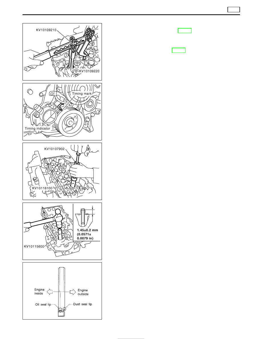
VALVE OIL SEAL
1. Remove timing chain. Refer to EM-26, “TIMING CHAIN”.
2. Remove injection nozzle assembly. Refer to “Injection Tube and
Injection Nozzle” in “BASIC SERVICE PROCEDURE” in EC
section.
3. Remove camshaft. Refer to EM-30, “CAMSHAFT”.
4. Remove valve lifters and mark order No. on each lifter.
5. Replace valve oil seal according to the following procedure.
When replacing valve oil seal, set the corresponding piston at
TDC. Failure to do so causes the valve to drop into the cylin-
der.
1) Set No. 1 cylinder at TDC.
2) Remove valve springs and valve oil seals for No. 1 and No. 4
cylinders. Valve spring seats should not be removed.
3) Install new valve oil seals for No. 1 and No. 4 cylinders as
illustrated. Reinstall valve springs. (pink paint side toward cyl-
inder head)
4) Install valve spring retainers on intake valves and valve rotators
on exhaust valves, and remount valve assembly.
5) Set No. 2 cylinder at TDC.
6) Replace valve oil seals for No. 2 and No. 3 cylinders according
to steps 2) and 3).
7) Install valve lifters in original positions.
CRANKSHAFT OIL SEAL INSTALLING DIRECTION AND
MANNER
I
When installing crankshaft oil seals, be careful to install
them correctly, as shown in the figure.
I
Wipe off excess oil after installing oil seal.
SEM354G
SEM355G
SEM356G
SEM357G
SEM715A
OIL SEAL REPLACEMENT
ZD
EM-50