Nissan Terrano model r20 series 2004. Manual - part 31


  Index      Nissan     Nissan Terrano model r20 series 2004 - Service and Repair Manual


Search            


Content   ..  29  30  31  32   ..


Nissan Terrano model r20 series 2004. Manual - part 31


Removal and Installation

I

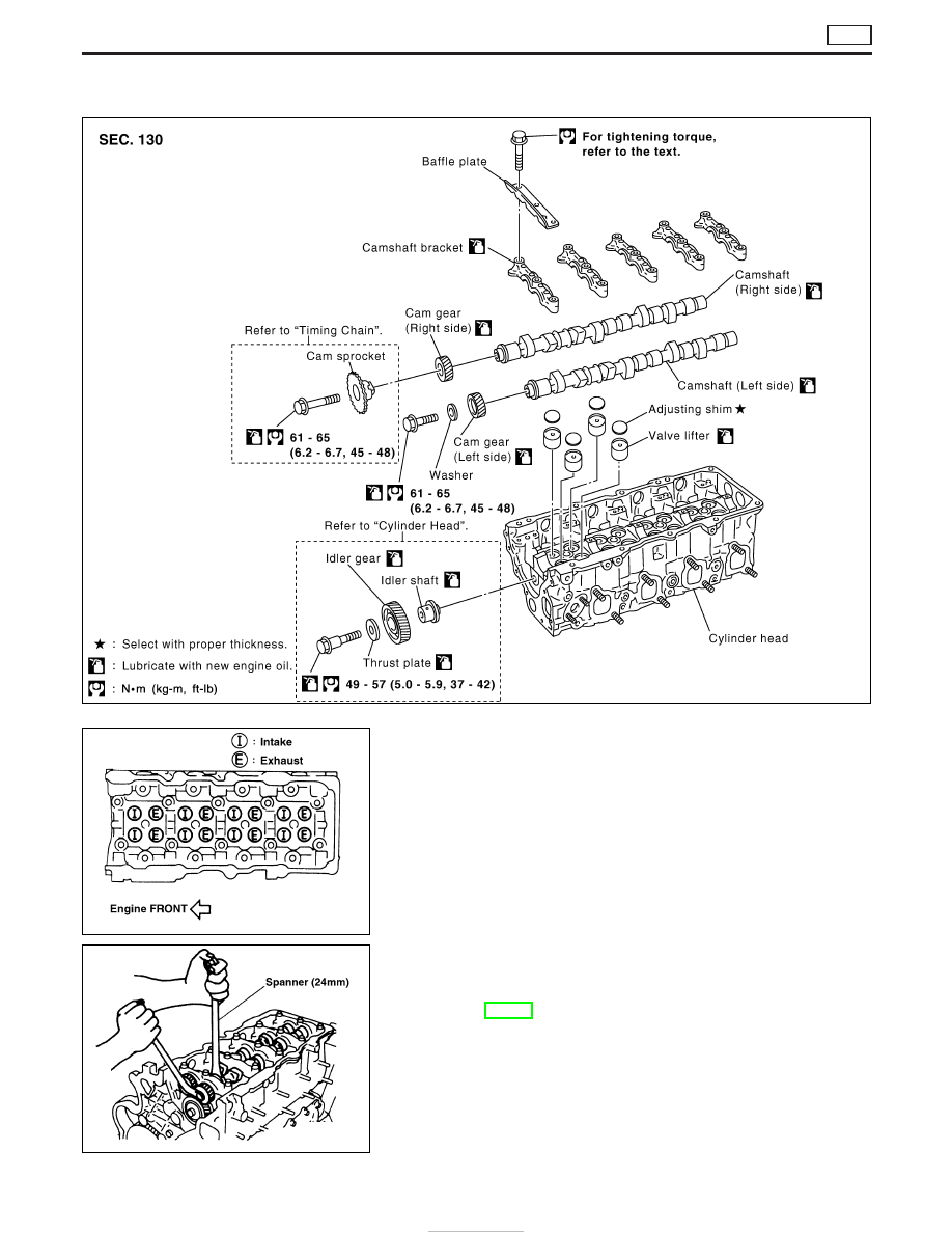
This engine will have a different valve arrangement from nor-
mal DOHC 4-valve type engines. As both camshafts on this
engine have intake and exhaust cams, in this chapter they are
named as follows:

Camshaft (Right side): Intake manifold side camshaft
Camshaft (Left side): Exhaust manifold side camshaft

I

The same parts are used for the right and left sides.

I

Refer to the figure for intake and exhaust valve arrangement.
(The camshafts have, alternately, either an intake valve or an
exhaust valve.)

Removal

1. Set the No. 1 cylinder at TDC, then remove the chain case,

timing chain and other parts in connection. Refer to “TIMING
CHAIN”, EM-26.

2. Remove the cam gear.

I

Loosen the cam gear installation bolt by fixing the hexagonal
portion of the camshaft.

I

The idler gear cannot be removed at this point as the gear case
is in the way. (The cylinder head can be removed as a single
unit.)

SEM350G

FEM010

FEM011

CAMSHAFT

ZD

EM-30

3. Remove injection tube and injection nozzle assembly. Refer to

EC section, “Injection Tube and Injection Nozzle” in “BASIC
SERVICE PROCEDURE”.

4. Remove the camshaft.

I

Place distinguishing marks on the right and left sides with paint.

I

Loosen and remove the installation bolt in reverse order shown
in the figure.

5. Remove the adjusting shim and valve lifter.

I

Remove by taking notice of the installation position, and place
outside engine in order to prevent confusion.

Inspection

VISUAL CHECK OF CAMSHAFT

I

Check the camshaft for one sided wear or scratches.

I

Replace the camshaft if there are abnormalities.

CAMSHAFT RUNOUT

I

Prepare V-block on a flat surface and secure camshaft journals
No. 1 and No. 5.

I

Set the dial gauge vertically on journal No. 3.

I

Rotate camshaft in one direction by hand, then read needle
movement on dial indicator.
Camshaft bend value is 1/2 of needle movement.

Limit: 0.02 mm (0.0008 in)

HEIGHT OF CAM NOSE

Measure by using a micrometer.

Standard:

Intake

40.468 - 40.508 mm (1.5932 - 1.5948 in)

Exhaust

40.830 - 40.870 mm (1.6075 - 1.6091 in)

CAMSHAFT OIL CLEARANCE

Measure by using a micrometer.

Cam journal outer diameter:

Standard

29.931 - 29.955 mm (1.1784 - 1.1793 in) dia.

FEM012

FEM013

FEM014

FEM015

CAMSHAFT

ZD

Removal (Cont’d)

EM-31

CAMSHAFT BRACKET INNER DIAMETER

I

Install camshaft bracket and tighten bolts to the specified
torque.

I

Measure inner diameter of camshaft bracket using an inside
micrometer.

Standard: 30.000 - 30.021 mm (1.1811 - 1.1819 in) dia.

CAMSHAFT OIL CLEARANCE CALCULATIONS

Oil clearance = Cam bracket inner diameter − Cam journal outer
diameter

Standard: 0.045 - 0.090 mm (0.0018 - 0.0035 in) dia.

I

If it exceeds the standard value, refer to the standard value of
each unit, then replace the camshaft and/or cylinder head.

I

As the camshaft bracket is manufactured with the cylinder
head, it is impossible to replace only the camshaft bracket.

CAMSHAFT END PLAY

I

Set the dial gauge to the front end of the camshaft. Measure
the end play by moving the camshaft in the direction of the axle.

Standard: 0.065 - 0.169 mm (0.0026 - 0.0067 in)
Limit: 0.2 mm (0.0079 in)

I

If end play exceeds the limit, replace camshaft and measure
camshaft end play again.

I

If end play still exceeds the limit after replacing camshaft,
replace cylinder head.

VISUAL INSPECTION OF VALVE LIFTER

Check lifter side for any signs of wear or damage. Replace if there
are any abnormalities.

VISUAL INSPECTION OF ADJUSTING SHIM

Check cam nose contact and sliding surfaces for wear and
scratches. Replace if there are any abnormalities.

VALVE LIFTER CLEARANCE

Measure the outer diameter of the valve lifter with a micrometer.

Standard: 34.455 - 34.465 mm (1.3565 - 1.3569 in) dia.

FEM016

FEM017

FEM018

CAMSHAFT

ZD

Inspection (Cont’d)

EM-32

VALVE LIFTER BORE DIAMETER

Measure the bore diameter of the cylinder head valve lifter with an
inside micrometer.

Standard: 34.495 - 34.515 mm (1.3581 - 1.3589 in) dia.

VALVE LIFTER CLEARANCE CALCULATIONS

Clearance = Valve lifter bore diameter − Valve lifter outer diameter

Standard: 0.030 - 0.060 mm (0.0012 - 0.0024 in)

If it exceeds the standard value, refer to the outer diameter and
bore diameter standard values and replace valve lifter and/or cyl-
inder head.

Installation

1. Install the valve lifter and adjusting shim.

I

Make sure that these are installed in the same position as
before the removal process.

2. Install the camshaft.

I

Follow the distinguishing marks that were placed on in the
removal process.

I

Face the key in the direction shown in the figure.

3. Install the camshaft bracket.

I

Refer to the camshaft bracket upper side journal No. and install.

I

Looking from the exhaust manifold side (left side of engine),
install in the direction that the journal number can be read cor-
rectly.

I

Place baffle plate onto upper face of No. 1 camshaft bracket,
and tighten together.

4. Tighten the installation bolts in numerical order in the figure.
1) Tighten to 10 to 14 N

m (1.0 to 1.5 kg-m, 8 to 10 ft-lb).

I

Make sure that the thrust portion of the camshaft is fitted prop-
erly in the head installation side.

2) Tighten to 20 to 23 N

m (2.0 to 2.4 kg-m, 15 to 17 ft-lb).

FEM019

FEM020

FEM021

FEM012

CAMSHAFT

ZD

Inspection (Cont’d)

EM-33


Content   ..  29  30  31  32   ..