Nissan Terrano r20e. Manual - part 309


  Index      Nissan     Nissan Terrano r20e - Service and Repair Manual


Search            


Content   ..  307  308  309  310   ..


Nissan Terrano r20e. Manual - part 309


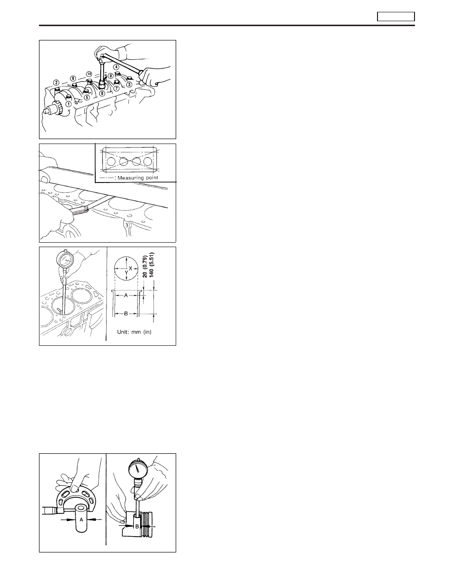
23. Remove bearing cap and crankshaft. Loosen bearing cap nuts

in numerical order, as shown at left.

Place the bearings and caps in their proper order.

Inspection

CYLINDER BLOCK DISTORTION

1. Clean upper face of cylinder block and measure the distortion.

Standard:

Less than 0.05 mm (0.0020 in)

Limit:

0.2 mm (0.008 in)

2. If out of specification, resurface it.

CYLINDER WEAR

1. Measure cylinder bore for out-of-round and taper with a bore

gauge. If beyond the limit, rebore all 4 cylinders. Replace cyl-
inder block if necessary.

Standard inside diameter:

96.000 - 96.030 mm (3.7795 - 3.7807 in)
Refer to SDS

Wear limit:

Less than 0.20 mm (0.0079 in)

Out-of-round (X − Y) limit:

Less than 0.020 mm (0.0008 in)

Taper (A − B) limit:

0.20 mm (0.0079 in)

2. Check for scratches or abrasions. If abrasions are found, hone

cylinder bore.

PISTON AND PISTON PIN CLEARANCE

Check clearance between pistons and piston pins.

Clearance (A − B):

Standard

−0.008 to 0.007 mm (−0.0003 to 0.0003 in)

Limit

Less than 0.1 mm (0.004 in)

NEM007

SEM038

MEM042A

NEM002

ENGINE OVERHAUL

TD27Ti

Disassembly (Cont’d)

EM-127

PISTON RING SIDE CLEARANCE

Side clearance:

Top ring

0.00 - 0.05 mm (0.0 - 0.0020 in)

2nd ring

0.04 - 0.072 mm (0.0016 - 0.0028 in)

Oil ring

0.035 - 0.040 mm (0.0014 - 0.0016 in)

Max. limit of side clearance:

Top ring

0.5 mm (0.020 in)

2nd ring

0.3 mm (0.012 in)

Oil ring

0.15 mm (0.0059 in)

PISTON RING END GAP

Standard ring gap:

Top ring

0.25 - 0.35 mm (0.0098 - 0.0138 in)

2nd ring

0.50 - 0.75 mm (0.0197 - 0.0295 in)

Oil ring

0.25 - 0.55 mm (0.0098 - 0.0217 in)

Max. limit of ring gap:

1.5 mm (0.059 in)

BEARING CLEARANCE

Main bearing

1. Install main bearings to cylinder block and main bearing cap.
2. Install main bearing cap to cylinder block.
Tighten all bolts in correct order and in two or three stages.
3. Measure inside diameter “A” of main bearing.

4. Measure outside diameter “Dm” of main journal in crankshaft.

EEM117

SEM905

YEM044

YEM045

ENGINE OVERHAUL

TD27Ti

Inspection (Cont’d)

EM-128

5. Calculate main bearing clearance.

Main bearing clearance = A − Dm

Standard

0.035 - 0.087 mm (0.0014 - 0.0034 in)

Limit

Less than 0.15 mm (0.0059 in)

CONNECTING ROD BEARING (Big end)

1. Install connecting rod bearing to connecting rod and cap.
2. Install connecting rod cap to connecting rod.
Apply oil to the thread portion of bolts and seating surface of
nuts.
3. Measure inside diameter “A” of bearing.
4. Measure outside diameter “Dp” of pin journal in crankshaft.
5. Calculate connecting rod bearing clearance.

Connecting rod bearing clearance = A − Dp

Standard

0.035 - 0.081 mm
(0.0014 - 0.0032 in)

Limit

Less than 0.15 mm (0.0059 in)

CONNECTING ROD BEND AND TORSION

Bend and torsion:

Limit

0.15 mm (0.0059 in)

per 200 mm (7.87 in) length

CONNECTING ROD BUSHING CLEARANCE (Small end)

1. Measure inside diameter “A” of connecting rod small end bush-

ings.

YEM046

EM133

YEM047

ENGINE OVERHAUL

TD27Ti

Inspection (Cont’d)

EM-129

2. Measure outside diameter “D” of piston pin.
3. Calculate connecting rod small end bushing clearance.

Connecting rod small end bushing clearance = A − D

Standard

0.025 - 0.045 mm (0.0010 - 0.0018 in)

Limit

0.15 mm (0.0059 in)

REPLACEMENT OF CONNECTING ROD BUSHING
(Small end)

1. Drive in the small end bushing until it is flush with the end sur-

face of the rod.

Be sure to align the oil holes.
2. After driving in the small end bushing, ream the bushing.

Small end bushing inside diameter:

Finished size

30.025 - 30.038 mm (1.1821 - 1.1826 in)

CRANKSHAFT

1. Check crankshaft journals and pins for score, bias, wear or

cracks. If faults are minor, correct with fine emery paper.

2. Check journals and pins with a micrometer for taper and out-

of-round.

Out-of-round (X − Y):

Standard

Less than 0.01 mm (0.0004 in)

Limit

0.02 mm (0.0008 in)

Taper (A − B):

Standard

Less than 0.01 mm (0.0004 in)

Limit

0.02 mm (0.0008 in)

3. Check crankshaft runout.

Runout (Total Indicator Reading)

Standard

0 - 0.03 mm (0 - 0.0012 in)

Limit

0.10 mm (0.0039 in)

SEM416B

EM715

SEM662B

ENGINE OVERHAUL

TD27Ti

Inspection (Cont’d)

EM-130


Content   ..  307  308  309  310   ..