Index Nissan Nissan Terrano r20e - Service and Repair Manual
Search
Content .. 199 200 201 202 ..
Nissan Terrano r20e. Manual - part 201
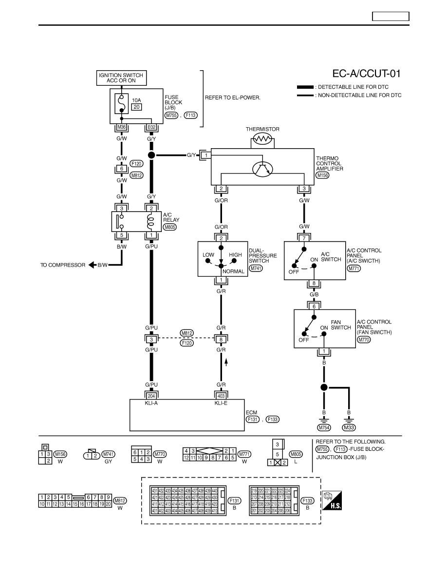
Wiring Diagram
LHD MODELS
YEC154A
DTC P1530 AIR CONDITIONER RLY
TD27Ti
EC-441