Nissan Terrano r20e. Manual - part 197


  Index      Nissan     Nissan Terrano r20e - Service and Repair Manual


Search            


Content   ..  195  196  197  198   ..


Nissan Terrano r20e. Manual - part 197


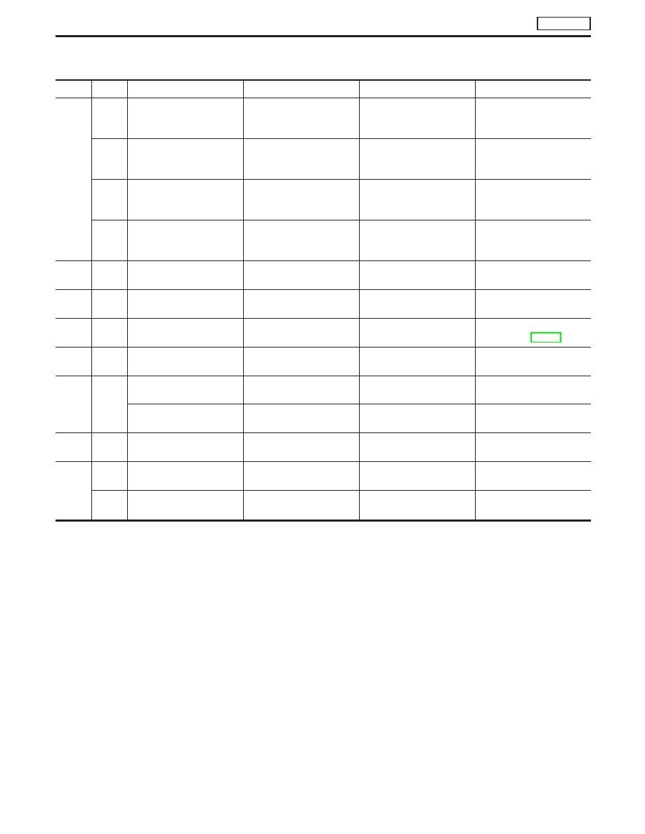
Main 12 Causes of Overheating

Engine

Step

Inspection item

Equipment

Condition

Reference page

OFF

1

I

Blocked radiator

I

Blocked radiator grille

I

Blocked bumper

I

Visual

No blocking

2

I

Coolant mixture

I

Coolant tester

50 - 50% coolant mixture

See MA section, “RECOM-
MENDED FLUIDS AND
LUBRICANTS”.

3

I

Coolant level

I

Visual

Coolant up to MAX level in
reservoir tank and radiator
filler neck

See LC section, “Changing
Engine Coolant”.

4

I

Radiator cap

I

Pressure tester

78 - 98 kPa (0.78 - 0.98
bar, 0.8 - 1.0 kg/cm

2, 11 - 14

psi)

See LC section, “System
Check”.

ON*

2

5

I

Coolant leaks

I

Visual

No leaks

See LC section, “System
Check”.

ON*

2

6

I

Thermostat

I

Touch the upper and
lower radiator hoses

Both hoses should be hot

See LC section, “Thermo-
stat” and “Radiator”.

ON*

1

7

I

Cooling fan

I

CONSULT-II

Operating

See Trouble Diagnosis for
DTC P1217, EC-418.

OFF

8

I

Combustion gas leak

I

Color checker chemical
tester 4 Gas analyzer

Negative

ON*

3

9

I

Coolant temperature
gauge

I

Visual

Gauge less than 3/4 when
driving

I

Coolant overflow to res-
ervoir tank

I

Visual

No overflow during driving
and idling

See LC section, “Changing
Engine Coolant”.

OFF*

4

10

I

Coolant return from res-
ervoir tank to radiator

I

Visual

Should be initial level in
reservoir tank

See LC section, “REFILL-
ING ENGINE COOLANT”.

OFF

11

I

Cylinder head

I

Straight gauge feeler
gauge

0.1 mm (0.004 in) Maxi-
mum distortion (warping)

See EM section, “Inspec-
tion”.

12

I

Cylinder block and pis-
tons

I

Visual

No scuffing on cylinder
walls or piston

See EM section, “Inspec-
tion”.

*1: Turn the ignition switch ON.
*2: Engine running at 3,000 rpm for 10 minutes.
*3: Drive at 90 km/h (55 MPH) for 30 minutes and then let idle for 10 minutes.
*4: After 60 minutes of cool down time.
For more information, refer to LC section, “OVERHEATING CAUSE ANALYSIS”.

DTC P1217 OVER HEAT

TD27Ti

EC-425

Component Inspection

COOLING FAN RELAY AND A/C RELAY

1. Turn ignition switch OFF.
2. Disconnect cooling fan relay and A/C relay.
3. Check continuity between each relay terminal

q

3

and

q

5

under

the following conditions.

Apply 12V direct current between
relay terminals

q

1

and

q

2

.

Continuity should exist.

No voltage applied.

Continuity should not exist.

4. If NG, replace cooling fan relay or/and A/C relay(s).

MEC942D

DTC P1217 OVER HEAT

TD27Ti

EC-426

Component Description

NEEDLE LIFT SENSOR (NLS)

The needle lift sensor is built into the No. 1 nozzle. Its inductive
pickup element senses fuel injection timing. It is sent as a pulse
signal to the ECM for feed-back the actual fuel injection timing and
calculating the secondary engine speed.

On Board Diagnosis Logic

DTC

Malfunction is detected when ....

Check Items

(Possible Cause)

P1240
0304

I

An incorrect signal from the sensor is sent to ECM.

I

Harness or connectors
(The sensor circuit is open or short-circuited.)

I

Needle lift sensor

P1242
0906

DTC Confirmation Procedure

NOTE:
Before DTC confirmation, be sure to check battery voltage is
above 9V.

WITH CONSULT-II

1) Turn ignition switch to “ON” position and select “DATA MONI-

TOR” mode with CONSULT-II.

2) Start engine.
3) Run it for 2 seconds at above 1,200 rpm.

WITHOUT CONSULT-II

1) Start engine.
2) Run it for 2 seconds at above 1,200 rpm.
3) Turn ignition switch to “LOCK” position, wait at least 5 seconds

and then turn to “ON” position.

4) Perform “Diagnostic Test Mode II” (Self-diagnostic results).

NEF689

DTC P1240 NEEDLE LIFT SEN, DTC P1242 NEEDLE LIFT SE

(RPM)

TD27Ti

EC-427

Wiring Diagram

YEC157A

DTC P1240 NEEDLE LIFT SEN, DTC P1242 NEEDLE LIFT SE

(RPM)

TD27Ti

EC-428


Content   ..  195  196  197  198   ..