Nissan Terrano r20e. Manual - part 196
Diagnostic Procedure
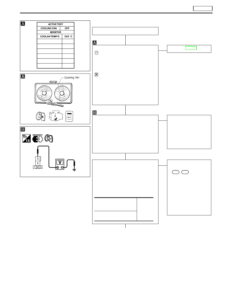
INSPECTION START
CHECK OVERALL FUNCTION.
With CONSULT-II
1. Turn ignition switch “ON”.
2. Perform “COOLING FAN” in “ACTIVE
TEST” mode with CONSULT-II.
3. Make sure that cooling fan operate.
Without CONSULT-II
1. Start engine and let it idle.
2. Set temperature lever at full cold posi-
tion.
3. Turn air conditioner switch “ON”.
4. Turn blower fan switch “ON”.
5. Make sure that cooling fan operate.
NG
E
OK
Go to “
q
C
”, EC-424.
CHECK COOLING FAN RELAY POWER
SUPPLY CIRCUIT.
1. Turn ignition switch “OFF”.
2. Disconnect cooling fan relay.
3. Check voltage between cooling fan
relay terminal
q
3
and ground with
CONSULT-II or tester.
Voltage: Battery voltage
OK
E
NG
Check the following.
I
30A fuse
I
Harness for open or
short between cooling
fan relay and battery
If NG, repair or replace
harness or fuse.
CHECK COOLING FAN MOTOR AND
CONDENSER CIRCUIT.
1. Disconnect cooling fan relay harness
connector, cooling fan motor harness
connector and condenser harness con-
nector.
2. Check continuity as follows. Refer to
wiring diagram.
OK
E
NG
Check the following.
I
Harness connectors
M785
,
F67
I
Harness for open or
short between cooling
fan relay and cooling fan
motor
I
Harness for open or
short between cooling
fan relay and condenser
If NG, repair harness or
connectors.
q
A
Cooling fan relay terminal
q
5
and cooling fan motor terminal
q
1
Continuity
should
exist.
Cooling fan relay terminal
q
5
and condenser terminal
q
1
SEF646X
SEC163BA
MEC940D
H
H
H
H
DTC P1217 OVER HEAT
TD27Ti
EC-421