Nissan Terrano r20e. Manual - part 193


  Index      Nissan     Nissan Terrano r20e - Service and Repair Manual


Search            


Content   ..  191  192  193  194   ..


Nissan Terrano r20e. Manual - part 193


Component Description
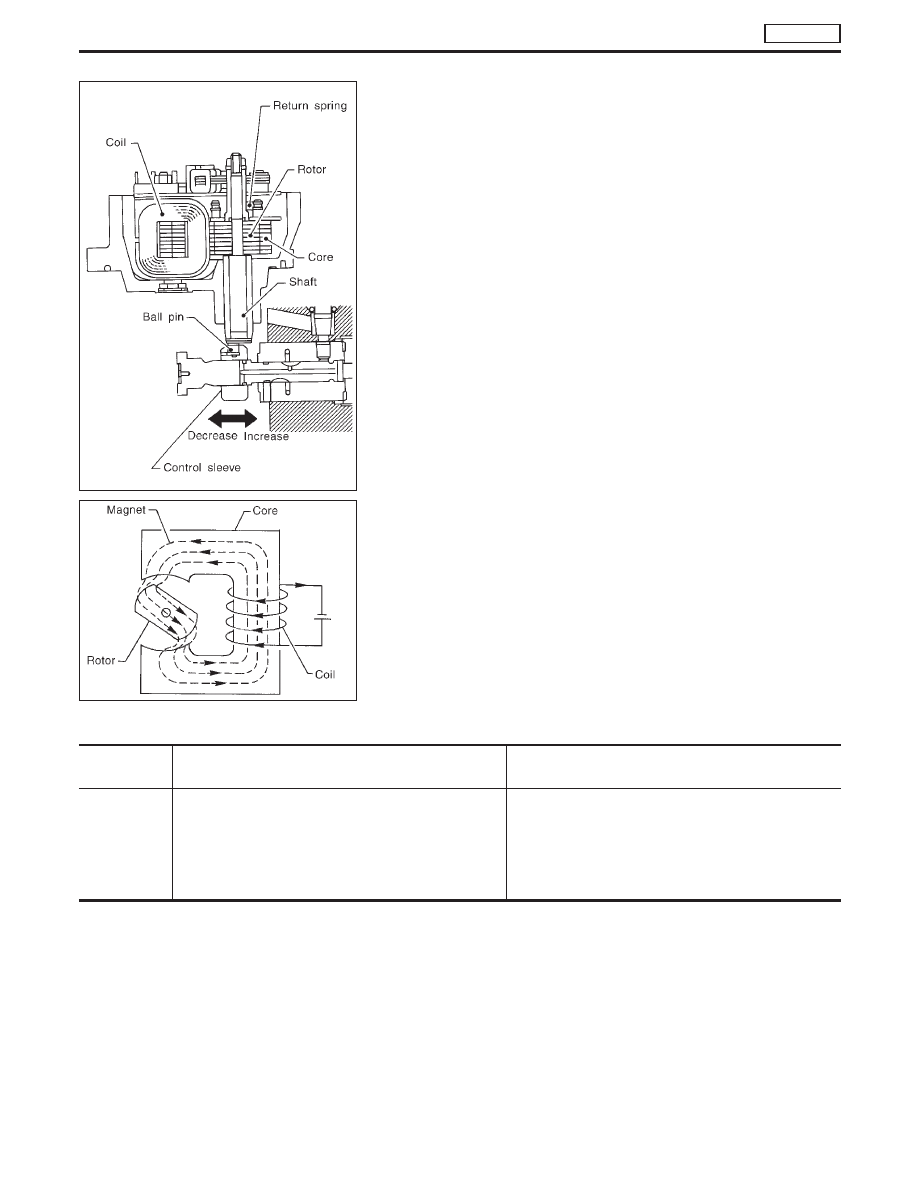
ELECTRIC GOVERNOR

The electric governor is built into the fuel injection pump. It moves
the control sleeve to increase or decrease the amount of fuel
injected.
When current flows through the coil, a magnetic force is produced,
rotating the rotor. The rotor shaft is installed to the control sleeve
via a ball pin which is eccentrically situated in relation to the rotor
shaft. With this arrangement, the control sleeve can be moved in
relation to rotor rotation.
The rotor’s rotating angle is determined by a balanced condition of
magnetic force (generated by current flow regulated by means of
the ECM) and tension of return spring (installed to rotor). The larger
the current flow through the coil, the greater the rotor’s rotating
angle. This means that the control sleeve moves to the right,
increasing the amount of fuel injected.
The ECM regulates the current flow through the coil by changing
the duty cycle ratio which controls the ON-OFF operation of the
electric governor grounding circuit.

On Board Diagnosis Logic

DTC

Malfunction is detected when ....

Check Items

(Possible cause)

P1206
0108

I

Fuel injection feedback system does not operate
properly. [This system consists essentially of ECM,
electric governor and control sleeve position sensor.]

I

Main power supply circuit

I

Harness or connectors
(Electric governor and control sleeve position sensor
circuit)

I

Electric governor

I

ECM

SEF632S

SEF633S

DTC P1206 F/INJ F/B 2

TD27Ti

EC-409

DTC Confirmation Procedure

WITH CONSULT-II

1) Turn ignition switch to “ON” position and select “DATA MONI-

TOR” mode with CONSULT-II.

2) Start engine above 1,200 rpm.
3) Run it for 2 seconds above 1,200 rpm. Return engine speed to

idle.

WITHOUT CONSULT-II

1) Start engine above 1,200 rpm.
2) Run engine for 2 seconds above 1,200 rpm. Return engine

speed to idle.

3) Turn ignition switch to “LOCK” position, wait at least 5 seconds

and then turn to “ON” position.

4) Perform “Diagnostic Test Mode II” (Self-diagnostic results).

NOTE:
If malfunction occurs intermittently, conduct suitable driving
pattern for 10 minutes. This makes it possible to determine
DTC.

DTC P1206 F/INJ F/B 2

TD27Ti

EC-410

Wiring Diagram

YEC149A

DTC P1206 F/INJ F/B 2

TD27Ti

EC-411

Diagnostic Procedure

INSPECTION START

CHECK MAIN POWER SUPPLY.
Refer to EC-352.

CHECK POWER SUPPLY CIRCUIT.
1. Turn ignition switch to “LOCK” position.
2. Disconnect ECM harness connector

and electronic injection pump harness
connector.

3. Check harness continuity between

injection pump connector terminal

q

7

and ECM connector terminals

107

,

108

,

109

. Refer to wiring diagram.

Continuity should exist.

4. Check harness continuity between

injection pump connector terminal

q

7

and ECM relay terminal

q

5

.

Refer to wiring diagram.
Continuity should exist.
If OK, check harness for short-circuit.

OK

E

NG

Check the following.

I

Harness connector

M787

,

F66

(LHD models)

I

Harness for open or
short between electronic
control injection pump
and ECM relay

I

Harness for open or
short between electronic
control injection pump
and ECM

If NG, repair harness or
connectors.

CHECK GROUND CIRCUIT.
Check harness continuity between injec-
tion pump connector terminal

q

4

and ECM

connector terminals

101

,

102

,

103

.

Refer to wiring diagram.
Continuity should exist.
If OK, check harness for short-circuit.

OK

E

NG

Repair harness or connec-
tors.

CHECK COMPONENT
(Electric governor).
Refer to “COMPONENT INSPECTION” on
next page.

OK

E

NG

Have the injection pump
assembly serviced by an
authorised service repre-
sentative.

Disconnect and reconnect harness connec-
tors in the circuit. Then retest.

Trouble is not fixed.

Check ECM pin terminals for damage and
check the connection of ECM harness con-
nector. Reconnect ECM harness connector
and retest.

INSPECTION END

YEC248A

H

H

H

H

H

H

H

DTC P1206 F/INJ F/B 2

TD27Ti

EC-412


Content   ..  191  192  193  194   ..