Nissan Terrano r20e. Manual - part 48


  Index      Nissan     Nissan Terrano r20e - Service and Repair Manual


Search            


Content   ..  46  47  48  49   ..


Nissan Terrano r20e. Manual - part 48


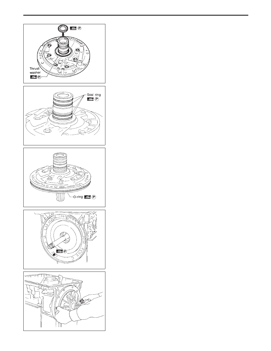
4. Install oil pump assembly.
a. Install needle bearing on oil pump assembly.

I

Apply petroleum jelly to the needle bearing.

b. Install selected thrust washer on oil pump assembly.

I

Apply petroleum jelly to thrust washer.

c. Carefully install seal rings into grooves and press them into the

petroleum jelly so that they are a tight fit.

d. Install O-ring on oil pump assembly.

I

Apply petroleum jelly to O-ring.

e. Apply petroleum jelly to mating surface of transmission case

and oil pump assembly.

f.

Install oil pump assembly.

I

Install two converter housing securing bolts in bolt holes
in oil pump assembly as guides.

SAT989A

SAT990A

SAT991A

SAT992A

SAT993A

ASSEMBLY

Assembly (2) (Cont’d)

AT-189

I

Insert oil pump assembly to the specified position in
transmission, as shown at left.

5. Install O-ring on input shaft.

I

Apply ATF to O-rings.

6. Install converter housing.
a. Apply recommended sealant (Nissan genuine part: KP610-

00250 or equivalent) to outer periphery of bolt holes in con-
verter housing.

I

Do not apply too much sealant.

b. Apply recommended sealant (Nissan genuine part: KP610-

00250 or equivalent) to seating surfaces of bolts that secure
front of converter housing.

c. Install converter housing on transmission case.

7. Adjust brake band.
a. Tighten anchor end bolt to specified torque.

Anchor end bolt:

: 4 - 6 N

m

(0.4 - 0.6 kg-m, 35 - 52 in-lb)

b. Back off anchor end bolt two and a half turns.

SAT994A

SAT114B

SAT397C

SAT158G

SAT001B

ASSEMBLY

Assembly (2) (Cont’d)

AT-190

c. While holding anchor end pin, tighten lock nut.

8. Install terminal cord assembly.
a. Install O-ring on terminal cord assembly.

I

Apply petroleum jelly to O-ring.

b. Compress terminal cord assembly stopper and install terminal

cord assembly on transmission case.

9. Install control valve assembly.
a. Install accumulator piston return springs

q

B

,

q

C

and

q

D

.

Free length of return springs:

Refer to SDS, AT-197.

b. Install manual valve on control valve.

I

Apply ATF to manual valve.

c. Place control valve assembly on transmission case. Connect

solenoid connector for upper body.

d. Install connector clip.

SAT002B

SAT115B

SAT004BA

SAT005B

SAT006B

ASSEMBLY

Assembly (2) (Cont’d)

AT-191

e. Install control valve assembly on transmission case.
f.

Install connector tube brackets and tighten bolts

q

A

and

q

B

.

I

Check that terminal assembly does not catch.

Bolt symbol


mm (in)

q

A

33 (1.30)

q

B

45 (1.77)

g. Install O-ring on oil strainer.

I

Apply petroleum jelly to O-ring.

h. Install oil strainer on control valve.

i.

Securely fasten terminal harness with clips.

j.

Install torque converter clutch solenoid valve and fluid tempera-
ture sensor connectors.

SAT353B

SAT221B

SAT009B

SAT010B

ASSEMBLY

Assembly (2) (Cont’d)

AT-192


Content   ..  46  47  48  49   ..