Nissan Terrano r20e. Manual - part 38
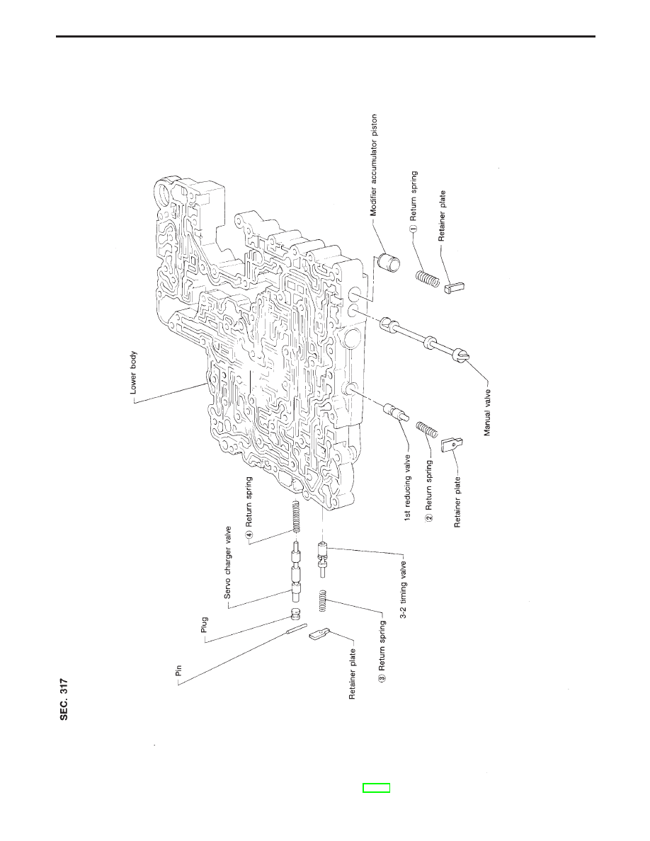
Control Valve Lower Body
Apply ATF to all components before their installation.
Numbers preceding valve springs correspond with those shown in SDS on page AT-197.
SAT112GA
REPAIR FOR COMPONENT PARTS
AT-149
|
|
|
Control Valve Lower Body Apply ATF to all components before their installation. Numbers preceding valve springs correspond with those shown in SDS on page AT-197. SAT112GA REPAIR FOR COMPONENT PARTS AT-149 |