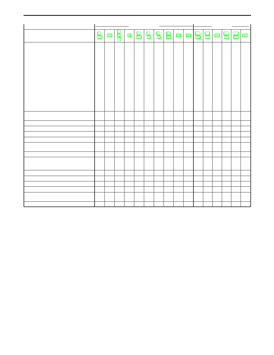
Nissan Terrano r20e. Manual - part 12
F
ON vehicle
E F
OFF vehicle
E
Reference page (AT-
)
Numbers are arranged in order of probability.
Perform inspections starting with number one and
work up. Circled numbers indicate that the transmis-
sion must be removed from the vehicle.
Fluid
level
Control
linkage
Park/neutral
position
switch
Throttle
(accelerator)
position
sensor
(Adjustment)
Revolution
sensor
and
vehicle
speed
sensor
Engine
speed
signal
Engine
idling
speed
Line
pressure
Control
valve
assembly
Shift
solenoid
valve
A
Shift
solenoid
valve
B
Line
pressure
solenoid
valve
T
orque
converter
clutch
solenoid
valve
Overrun
clutch
solenoid
valve
A/T
fluid
temperature
sensor
Accumulator
N-D
Accumulator
1-2
Accumulator
2-3
Accumulator
3-4
(N-R)
Ignition
switch
and
starter
T
orque
converter
Oil
pump
Reverse
clutch
High
clutch
Forward
clutch
Forward
one-way
clutch
Overrun
clutch
Low
one-way
clutch
Low
&
reverse
brake
Brake
band
Parking
pawl
components
Failure to change from “D
3
” to “2” when changing
lever into “2” position.
.
7
1
2
.
.
.
.
6
5
4
.
.
3
.
.
.
.
.
.
.
.
.
.
.
.
q
9
.
.
q
8
.
Gear change from “2
1
” to “2
2
” in “2” position.
.
.
1
.
.
.
.
.
.
.
.
.
.
.
.
.
.
.
.
.
.
.
.
.
.
.
.
.
.
.
.
Engine brake does not operate in “1” position.
.
2
1
3
4
.
.
.
6
5
.
.
.
7
.
.
.
.
.
.
.
.
.
.
.
.
q
8
.
q
9
.
.
Gear change from “1
1
” to “1
2
” in “1” position.
.
2
1
.
.
.
.
.
.
.
.
.
.
.
.
.
.
.
.
.
.
.
.
.
.
.
.
.
.
.
.
Does not change from “1
2
” to “1
1
” in “1” position.
.
.
1
.
2
.
.
.
4
3
.
.
.
5
.
.
.
.
.
.
.
.
.
.
.
.
q
6
.
q
7
.
.
Large shock changing from “1
2
” to “1
1
” in “1” posi-
tion.
.
.
.
.
.
.
.
.
1
.
.
.
.
.
.
.
.
.
.
.
.
.
.
.
.
.
.
.
q
2
.
.
Transmission overheats.
1
.
.
3
.
.
2
4
6
.
.
5
.
.
.
.
.
.
.
.
q
14
q
7
q
8
q
9
q
11
.
q
12
.
q
13
q
10
.
ATF shoots out during operation.
White smoke emitted from exhaust pipe during
operation.
1
.
.
.
.
.
.
.
.
.
.
.
.
.
.
.
.
.
.
.
.
.
q
2
q
3
q
5
.
q
6
.
q
7
q
4
.
Offensive smell at fluid charging pipe.
1
.
.
.
.
.
.
.
.
.
.
.
.
.
.
.
.
.
.
.
q
2
q
3
q
4
q
5
q
7
.
q
8
.
q
9
q
6
.
Torque converter is not locked up.
.
.
3
1
2
4
.
6
8
.
.
.
7
.
5
.
.
.
.
.
q
9
.
.
.
.
.
.
.
.
.
.
Torque converter clutch piston slip
1
.
.
2
.
.
.
3
6
.
.
5
4
.
.
.
.
.
.
.
q
7
.
.
.
.
.
.
.
.
.
.
Lock-up point is extremely high or low.
.
.
.
1
2
.
.
.
4
.
.
.
3
.
.
.
.
.
.
.
.
.
.
.
.
.
.
.
.
.
.
A/T does not shift to “D
4
” when driving with over-
drive control switch “ON”.
.
.
2
1
3
.
.
8
6
4
.
.
.
5
7
.
.
.
.
.
.
.
.
.
.
.
q
10
.
.
q
9
.
Engine is stopped at “R”, “D”, “2” and “1” positions.
1
.
.
.
.
.
.
.
5
4
3
.
2
.
.
.
.
.
.
.
.
.
.
.
.
.
.
.
.
.
.
TROUBLE DIAGNOSIS — General Description
Symptom Chart (Cont’d)
AT-45