Nissan Titan. Manual - part 661


  Index      Nissan     Nissan Titan (2014 year) - Service and Repair Manual


Search            


Content   ..  659  660  661  662   ..


Nissan Titan. Manual - part 661


TPMS

WT-9

< SYSTEM DESCRIPTION >

C

D

F

G

H

I

J

K

L

M

A

B

WT

N

O

P

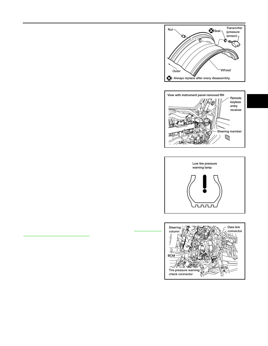
A sensor-transmitter integrated with a valve is installed in each

wheel, and transmits a detected air pressure signal in the form of a

radio wave. The radio signal is received by the remote keyless entry

receiver.

REMOTE KEYLESS ENTRY RECEIVER

The remote keyless entry receiver is shown with the instrument

panel RH removed. The remote keyless entry receiver receives the

air pressure signal transmitted by the transmitter in each wheel.

COMBINATION METER

The combination meter receives tire pressure status from the BCM

using CAN communication. When a low tire pressure condition is

sensed by the BCM, the combination meter low tire pressure warn-

ing lamp is activated. A CHECK TIRE PRESSURE warning mes-

sage will also be displayed in the vehicle information display. Refer

to the Owner’s Manual for additional information.

TIRE PRESSURE WARNING CHECK CONNECTOR

The tire pressure warning check connector can be grounded in order

to initiate self-diagnosis without CONSULT. Refer to 

WT-12, "Self-

Diagnosis (Without CONSULT)"

. The tire pressure warning check

connector is located behind the lower portion of the instrument panel

LH.

WEIA0137E

LEIA0069E

LEIA0055E

LEIA0068E

WT-10

< SYSTEM DESCRIPTION >

TPMS

System Component

INFOID:0000000009885631

AWEIA0288ZZ

1.

Tire pressure warning check connec-
tor M123

2.

Transmitter

3.

BCM
M18, M20

4.

Combination meter
M24

5.

Remote keyless entry receiver
M120

DIAGNOSIS SYSTEM (BCM)

WT-11

< SYSTEM DESCRIPTION >

C

D

F

G

H

I

J

K

L

M

A

B

WT

N

O

P

DIAGNOSIS SYSTEM (BCM)

CONSULT Function (BCM - COMMON ITEM)

INFOID:0000000009885632

APPLICATION ITEM

CONSULT performs the following functions via CAN communication with BCM.

SYSTEM APPLICATION

BCM can perform the following functions.

CONSULT Function (BCM - AIR PRESSURE MONITOR)

INFOID:0000000009885633

NOTE:

Direct Diagnostic Mode

Description

Ecu Identification

The BCM part number is displayed.

Self Diagnostic Result

The BCM self diagnostic results are displayed.

Data Monitor

The BCM input/output data is displayed in real time.

Active Test

The BCM activates outputs to test components.

Work support

The settings for BCM functions can be changed.

Configuration

• The vehicle specification can be read and saved.
• The vehicle specification can be written when replacing BCM.

CAN Diag Support Mntr

The result of transmit/receive diagnosis of CAN communication is displayed.

System

Sub System

Direct Diagnostic Mode

Ecu Id

en

tificati

on

Sel

f Di

agn

os

tic Re

su

lt

Dat

a

 M

on

ito

r

Acti

ve

 T

est

W

ork

 su

pp

ort

Co

nf

ig

ur

at

io

n

CAN Diag S

upport Mntr

Door lock

DOOR LOCK

×

×

×

Rear window defogger

REAR DEFOGGER

×

×

Warning chime

BUZZER

×

×

Interior room lamp timer

INT LAMP

×

×

×

Remote keyless entry system

MULTI REMOTE ENT

×

×

×

Exterior lamp

HEADLAMP

×

×

×

Wiper and washer

WIPER

×

×

×

Turn signal and hazard warning lamps FLASHER

×

×

Air conditioner

AIR CONDITIONER

×

Combination switch

COMB SW

×

BCM

BCM

×

×

×

×

×

Immobilizer

IMMU

×

×

×

Interior room lamp battery saver

BATTERY SAVER

×

×

×

Vehicle security system

THEFT ALM

×

×

×

RAP system

RETAINED PWR

×

×

×

Signal buffer system

SIGNAL BUFFER

×

×

TPMS

AIR PRESSURE MONITOR

×

×

×

×

Panic alarm system

PANIC ALARM

×

WT-12

< SYSTEM DESCRIPTION >

DIAGNOSIS SYSTEM (BCM)

The Signal Tech II Tool (J-50190) can be used to perform the following functions. Refer to the Signal Tech II

User Guide for additional information.

• Activate and display TPMS transmitter IDs

• Display tire pressure reported by the TPMS transmitter

• Read TPMS DTCs

• Register TPMS transmitter IDs

SELF DIAGNOSTIC RESULT

NOTE:

Before performing Self Diagnostic Result, be sure to register the ID, or else the actual malfunction may be dif-

ferent from that displayed on CONSULT.

Refer to 

BCS-42, "DTC Index"

.

DATA MONITOR

ACTIVE TEST

WORK SUPPORT

Self-Diagnosis (Without CONSULT)

INFOID:0000000009885634

NOTE:

The Signal Tech II Tool (J-50190) can be used to perform the following functions. Refer to the Signal Tech II

User Guide for additional information.

• Activate and display TPMS transmitter IDs

• Display tire pressure reported by the TPMS transmitter

• Read TPMS DTCs

• Register TPMS transmitter IDs

SELF DIAGNOSTIC PROCEDURE (WITHOUT CONSULT)

Monitor Item

Condition

Specification

VEHICLE SPEED

Drive vehicle

Vehicle speed (km/h or mph)

AIR PRESS FL 

• Drive vehicle for a few minutes.

                           or

• Ignition switch ON and activation tool is trans-

mitting activation signals.

Tire pressure (kPa, kg/cm

2

 or psi).

AIR PRESS FR

AIR PRESS RR

AIR PRESS RL

ID REGST FL1

Ignition switch ON.

Registration ID: Green.
No registration: Red.

ID REGST FR1

ID REGST RR1

ID REGST RL1

WARNING LAMP

Ignition switch ON.

Low tire pressure warning lamp on: ON.
Low tire pressure warning lamp off: OFF.

BUZZER

Ignition switch ON.

Buzzer in combination meter on: ON.
Buzzer in combination meter off: OFF.

Test Item

Description

WARNING LAMP

This test is able to check tire pressure warning lamp operation [Off/On].

ID REGIST WARNING

This test is able to check ID regist warning chime operation [Off/On].

FLAT TIRE WARNING

This test is able to check flat tire warning chime operation [Off/On].

HORN

This test is able to check horn operation [On].

FLASHER

This test is able to check turn signal lamp operation [Off/LH/RH].

Support Item

Description

ID REGIST

Refer to 

WT-6, "ID Registration Procedure"

.

ID READ

The registered ID number is displayed.


Content   ..  659  660  661  662   ..