Nissan Titan. Manual - part 541


  Index      Nissan     Nissan Titan (2014 year) - Service and Repair Manual


Search            


Content   ..  539  540  541  542   ..


Nissan Titan. Manual - part 541


SR-4

< REMOVAL AND INSTALLATION >

DRIVER AIR BAG MODULE

REMOVAL AND INSTALLATION

DRIVER AIR BAG MODULE

Removal and Installation

INFOID:0000000009882844

REMOVAL

CAUTION:

• Do not attempt to repair or replace damaged direct-connect SRS component connectors. If a driver

air bag direct-connect harness connector is damaged, the spiral cable must be replaced.

• Before servicing the SRS, turn ignition switch OFF, disconnect both battery terminals and wait at

least three minutes.

• When servicing the SRS, do not work from directly in front of air bag module.
1. Disconnect both the negative and positive battery terminals, then wait at least three minutes.  Refer to

PG-80, "Removal and Installation"

.

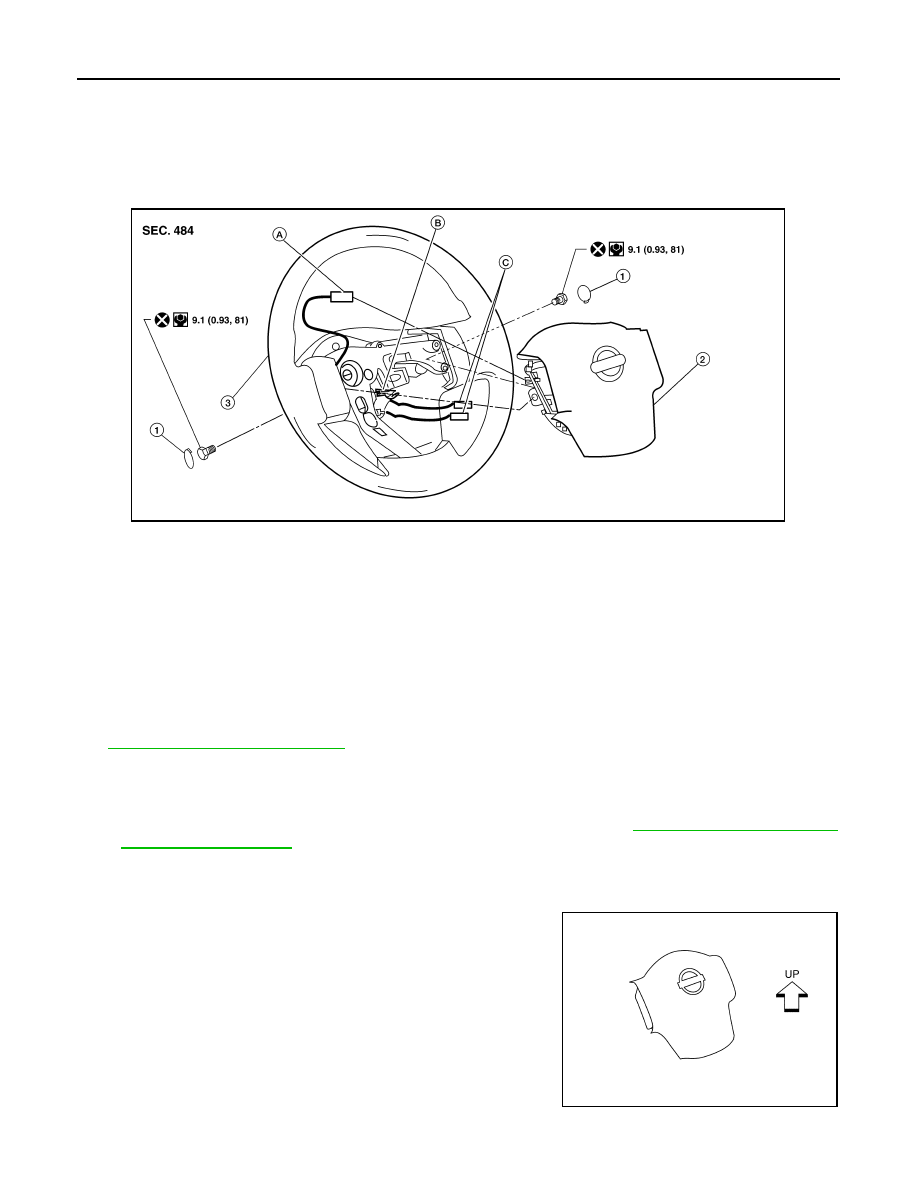
2. Remove the side lids (LH/RH) and the bolts.
3. Lift the driver air bag module from the steering wheel.
4. Disconnect the harness connectors from the air bag and horn, then remove the driver air bag module.

• For removal/installation of the direct-connect SRS connectors, refer to 

SRC-9, "Direct-connect SRS

Component Connectors"

.

CAUTION:

• When servicing the SRS, do not work from directly in front of air bag module.

• Always place air bag module with pad side facing upward.

• Do not insert any foreign objects (screwdriver, etc.) into air

bag module or harness connectors.

• Do not disassemble air bag module.

• Do not use old bolts after removal; replace with new bolts.

• Do not expose the air bag module to temperatures exceeding

90

°C (194°F).

1.

Side lids (LH/RH)

2.

Driver air bag module

3.

Steering wheel

A.

Horn harness connector

B.

Steering wheel hook

C.

Inflator harness connectors

AWHIA0461ZZ

LHIA0052E

DRIVER AIR BAG MODULE

SR-5

< REMOVAL AND INSTALLATION >

C

D

E

F

G

I

J

K

L

M

A

B

SR

N

O

P

• Replace the air bag module if it has been dropped or sus-

tained an impact.

• Do not allow oil, grease or water to come in contact with the

air bag module.

INSTALLATION

Installation is in the reverse order of removal.

• If driver air bag module is being replaced due to deployment, spiral cable must also be replaced. Refer to

SR-6, "Removal and Installation"

 .

• For removal/installation of the direct-connect SRS connectors, refer to 

SRC-9, "Direct-connect SRS Compo-

nent Connectors"

.

• After the work is completed, perform self-diagnosis to check that no malfunction is detected. Refer to 

SRC-

13, "SRS Operation Check"

.

SBF814E

SR-6

< REMOVAL AND INSTALLATION >

SPIRAL CABLE

SPIRAL CABLE

Removal and Installation

INFOID:0000000009882845

REMOVAL

CAUTION:

• Before servicing the SRS, turn ignition switch OFF, disconnect both battery terminals and wait at

least three minutes.

• When servicing the SRS, do not work from directly in front of air bag module.
1. Disconnect both the negative and positive battery terminals, then wait at least three minutes. Refer to 

PG-

80, "Removal and Installation"

.

2. Remove the steering wheel. Refer to 

ST-22, "Removal and Installation"

.

3. Remove the instrument lower panel LH. Refer to 

IP-17, "Removal and Installation"

.

4. Remove the steering column upper and lower covers.
5. Disconnect the harness connector from the wiper washer

switch, then pinch the tabs at wiper and washer switch base and

slide switch away from steering column to remove.

AWHIA0141GB

1.

Steering wheel

2.

Lighting and turn signal switch

3.

Wiper and washer switch

4.

Spiral cable

5.

Driver air bag module harness con-
nector

6.

Steering column upper cover

7.

Steering column assembly

8.

Steering column lower cover

9.

Screw (Do not remove)

10. Screw

A. 

Refer to 

ST-17, "Removal and Instal-

lation"

LHIA0034E

SPIRAL CABLE

SR-7

< REMOVAL AND INSTALLATION >

C

D

E

F

G

I

J

K

L

M

A

B

SR

N

O

P

6. While pressing tabs, pull lighting and turn signal switch toward

driver door and disconnect from base.

7. Remove the screws, release the clip, and remove the spiral

cable. 

CAUTION:

• Do not disassemble spiral cable.

• Do not apply lubricant to the spiral cable.

8. Disconnect the harness connectors from the spiral cable.

CAUTION:

With the steering linkage disconnected, the spiral cable may snap by turning the steering wheel

beyond the limited number of turns. The spiral cable can be turned counterclockwise about 2.5

turns from the neutral position.

9. Remove the steering angle sensor from the spiral cable. Refer to 

BRC-118, "Removal and Installation"

.

INSTALLATION

Installation is in the reverse order of removal.

• Align spiral cable correctly when installing steering wheel. Make

sure that the spiral cable is in the neutral position. The neutral

position is detected by turning left 2.5 revolutions from the right

end position and ending with the knob at the top.

• Refer to 

BRC-8, "ADJUSTMENT OF STEERING ANGLE SEN-

SOR NEUTRAL POSITION : Special Repair Requirement"

 for

steering angle sensor adjustment.

• After the work is completed, perform self-diagnosis to make sure

no malfunction is detected. Refer to 

SRC-13, "SRS Operation

Check"

.

CAUTION:

• The spiral cable may snap due to steering operation if the

cable is not installed in the correct position.

• With the steering linkage disconnected, the cable may snap

by turning the steering wheel beyond the limited number of

turns. The spiral cable can be turned counterclockwise about

2.5 turns from the neutral position.

LHIA0035E

LHIA0036E

WGIA0038E

PHIA0275E


Content   ..  539  540  541  542   ..