Nissan Titan. Manual - part 539
SEC-68
< SYMPTOM DIAGNOSIS >
VEHICLE SECURITY SYSTEM SYMPTOMS
SYMPTOM DIAGNOSIS
VEHICLE SECURITY SYSTEM SYMPTOMS
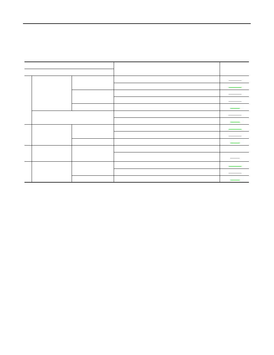
Symptom Table
INFOID:0000000009878913
*: Check the system is in the armed phase.
Procedure
Diagnostic procedure
Refer to page
Symptom
1
Vehicle security sys-
tem cannot be set by
····
Door switch
Check door switch (king cab)
Check door switch (crew cab)
Key cylinder switch
Check key cylinder switch (king cab)
Check key cylinder switch (crew cab)
—
Check Intermittent Incident
Security indicator does not turn ON.
Check vehicle security indicator
Check Intermittent Incident
2
* Vehicle security
system does not
sound alarm when ····
Any door is opened.
Check door switch (king cab)
Check door switch (crew cab)
—
Check Intermittent Incident
3
Vehicle security
alarm does not acti-
vate.
Horn alarm
Check horn switch
—
Check Intermittent Incident
4
Vehicle security sys-
tem cannot be can-
celed by ····
Key cylinder switch
Check key cylinder switch (king cab)
Check key cylinder switch (crew cab)
—
Check Intermittent Incident