Nissan Titan. Manual - part 540


  Index      Nissan     Nissan Titan (2014 year) - Service and Repair Manual


Search            


Content   ..  538  539  540  541   ..


Nissan Titan. Manual - part 540


SEC-72

< REMOVAL AND INSTALLATION >

REMOTE KEYLESS ENTRY RECEIVER

REMOTE KEYLESS ENTRY RECEIVER

Removal and Installation

INFOID:0000000009878917

REMOTE KEYLESS ENTRY RECEIVER

Removal

1. Remove the instrument lower panel RH. Refer to 

IP-16, "Removal and Installation"

.

2. Remove the side ventilator assembly RH. Refer to 

IP-10, "Exploded View"

.

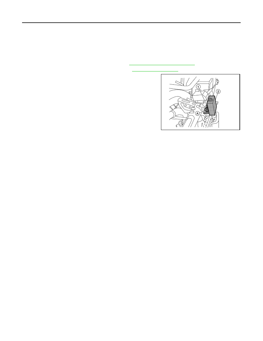
3. Remove the RKE receiver (2).
a. Disconnect the harness connector (1) from the RKE receiver.
b. Remove the RKE receiver bolt (A).

Installation

Installation is in the reverse order of removal.

ALKIA0537ZZ

SR-1

RESTRAINTS

C

D

E

F

G

I

J

K

L

M

SECTION 

SR

A

B

SR

N

O

P

CONTENTS

SRS AIRBAG

PRECAUTION ...............................................

2

PRECAUTIONS ...................................................

2

Precaution for Supplemental Restraint System 
(SRS) "AIR BAG" and "SEAT BELT PRE-TEN-
SIONER" .................................................................
..

2

Service ......................................................................

2

Occupant Classification System Precaution  .............

2

PREPARATION ............................................

3

PREPARATION ...................................................

3

Special Service Tool  .................................................

3

REMOVAL AND INSTALLATION ................

4

DRIVER AIR BAG MODULE ...............................

4

Removal and Installation ...........................................

4

SPIRAL CABLE  ..................................................

6

Removal and Installation ...........................................

6

FRONT PASSENGER AIR BAG MODULE  ........

8

Removal and Installation ...........................................

8

SIDE CURTAIN AIR BAG MODULE  ................

11

Removal and Installation  .........................................

11

SIDE AIR BAG MODULE ..................................

13

Removal and Installation  .........................................

13

CRASH ZONE SENSOR ...................................

14

Removal and Installation  .........................................

14

SIDE AIR BAG (SATELLITE) SENSOR  ...........

15

Removal and Installation  .........................................

15

FRONT SEAT BELT PRE-TENSIONER ...........

16

Removal and Installation  .........................................

16

DIAGNOSIS SENSOR UNIT  .............................

17

Removal and Installation  .........................................

17

OCCUPANT CLASSIFICATION SYSTEM 
CONTROL UNIT ................................................

19

Removal and Installation  .........................................

19

COLLISION DIAGNOSIS  ..................................

20

For Frontal Collision  ................................................

20

For Side and Rollover Collision ...............................

22

SR-2

< PRECAUTION >

PRECAUTIONS

PRECAUTION

PRECAUTIONS

Precaution for Supplemental Restraint System (SRS) "AIR BAG" and "SEAT BELT 
PRE-TENSIONER"

INFOID:0000000009882840

The Supplemental Restraint System such as “AIR BAG” and “SEAT BELT PRE-TENSIONER”, used along

with a front seat belt, helps to reduce the risk or severity of injury to the driver and front passenger for certain

types of collision. This system includes seat belt switch inputs and dual stage front air bag modules. The SRS

system uses the seat belt switches to determine the front air bag deployment, and may only deploy one front

air bag, depending on the severity of a collision and whether the front occupants are belted or unbelted.

Information necessary to service the system safely is included in the SR and SB section of this Service Man-

ual.

WARNING:

• To avoid rendering the SRS inoperative, which could increase the risk of personal injury or death in

the event of a collision which would result in air bag inflation, all maintenance must be performed by

an authorized NISSAN/INFINITI dealer.

• Improper maintenance, including incorrect removal and installation of the SRS, can lead to personal

injury caused by unintentional activation of the system. For removal of Spiral Cable and Air Bag

Module, see the SR section.

• Do not use electrical test equipment on any circuit related to the SRS unless instructed to in this

Service Manual. SRS wiring harnesses can be identified by yellow and/or orange harnesses or har-

ness connectors.

PRECAUTIONS WHEN USING POWER TOOLS (AIR OR ELECTRIC) AND HAMMERS

WARNING:

• When working near the Airbag Diagnosis Sensor Unit or other Airbag System sensors with the Igni-

tion ON or engine running, DO NOT use air or electric power tools or strike near the sensor(s) with a

hammer. Heavy vibration could activate the sensor(s) and deploy the air bag(s), possibly causing

serious injury.

• When using air or electric power tools or hammers, always switch the Ignition OFF, disconnect the

battery, and wait at least 3 minutes before performing any service.

Service

INFOID:0000000009882841

• Do not use electrical test equipment to check SRS circuits unless instructed to in this Service Manual.

• Before servicing the SRS, turn ignition switch OFF, disconnect both battery cables and wait at least three

minutes.

For approximately three minutes after the cables are removed, it is still possible for the air bag and seat belt

pre-tensioner to deploy. Therefore, do not work on any SRS connectors or wires until at least three minutes

have passed.

• Diagnosis sensor unit must always be installed with their arrow marks “

⇐” pointing towards the front of the

vehicle for proper operation. Also check diagnosis sensor unit for cracks, deformities or rust before installa-

tion and replace as required.

• The spiral cable must be aligned with the neutral position since its rotations are limited. Do not turn steering

wheel and column after removal of steering gear.

• Handle air bag module carefully. Always place driver and front passenger air bag modules with the pad side

facing upward and seat mounted front side air bag module standing with the stud bolt side facing down.

• Conduct self-diagnosis to check entire SRS for proper function after replacing any components.

• After air bag inflates, the instrument panel assembly should be replaced if damaged.

• Always replace instrument panel pad following front passenger air bag deployment.

Occupant Classification System Precaution

INFOID:0000000009882842

Replace occupant classification system control unit and passenger front seat cushion as an assembly.

PREPARATION

SR-3

< PREPARATION >

C

D

E

F

G

I

J

K

L

M

A

B

SR

N

O

P

PREPARATION

PREPARATION

Special Service Tool

INFOID:0000000009882843

The actual shapes of Kent-Moore tools may differ from those of special service tools illustrated here.

Tool number
(Kent-Moore No.)
Tool name

Description

(J-42057-UPD)
Air bag key set
Part of kit (J-42057)

Removing and installing air bag lock

LRS210


Content   ..  538  539  540  541   ..