Nissan Titan. Manual - part 355


  Index      Nissan     Nissan Titan (2014 year) - Service and Repair Manual


Search            


Content   ..  353  354  355  356   ..


Nissan Titan. Manual - part 355


KNUCKLE

FSU-19

< REMOVAL AND INSTALLATION >

C

D

F

G

H

I

J

K

L

M

A

B

FSU

N

O

P

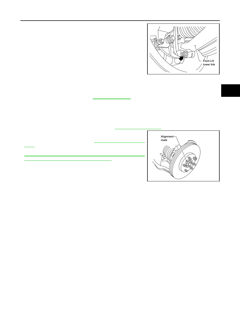
8. Remove the pinch bolt and nut from the steering knuckle using

power tool. Separate the lower link ball joint from the steering

knuckle.

9. Remove the steering knuckle from the vehicle.

INSPECTION AFTER REMOVAL

• Check for deformity, cracks and damage on each part, replace if necessary.

• Perform ball joint inspection. Refer to 

FSU-13, "Inspection"

.

INSTALLATION

Installation is in the reverse order of removal.

CAUTION:

• Do not reuse the lower link ball joint nut.

• Do not reuse the upper link ball joint cotter pin.

• Tighten all nuts and bolts to specification.Refer to 

FSU-10, "Exploded View"

.

• When installing disc rotor on wheel hub and bearing assembly,

align the marks.

• Check the wheel alignment. Refer to 

FSU-5, "Front Wheel Align-

ment"

.

• Adjust the neutral position of the steering angle sensor. Refer to

BRC-8, "ADJUSTMENT OF STEERING ANGLE SENSOR NEU-

TRAL POSITION : Special Repair Requirement"

.

LEIA0097E

WDIA0044E

FSU-20

< UNIT DISASSEMBLY AND ASSEMBLY >

COIL SPRING AND SHOCK ABSORBER

UNIT DISASSEMBLY AND ASSEMBLY

COIL SPRING AND SHOCK ABSORBER

Disassembly and Assembly

INFOID:0000000009885608

DISASSEMBLY

1. Set the coil spring and shock absorber in a vise.

CAUTION:

Do not remove the piston rod lock nut at this time.

2. Use a suitable bar to prevent the shock absorber mounting insu-

lator from turning.

3. Loosen (without removing) the piston rod lock nut as shown.
4. Compress the coil spring using spring compressors (commercial

service tools) until the shock absorber mounting insulator can be

turned by hand.

WARNING:

Make sure that the pawls of the spring compressors (com-

mercial service tools) are firmly hooked on the coil spring. The spring compressors (commercial

service tools) must be tightened alternately and evenly so as not to tilt the coil spring.

5. Remove the piston rod lock nut.
6. Remove the washer, the spacer, the shock absorber mounting

insulator, the shock absorber bushing, and the upper spring

seat.

7. Remove the dust cover and the upper seat.
8. Gradually release the spring compressors (commercial service

tools) and remove the coil spring.

INSPECTION AFTER DISASSEMBLY

Shock Absorber

• Check the shock absorber for smooth operation through a full stroke, both compression and extension.

• Check the shock absorber for oil leakage on welded or gland packing portions.

• Check the piston rod for cracks, deformation or other damage and replace if necessary.

Mounting Insulator and Rubber Parts

Check the cemented rubber-to-metal portion for separation or cracks. Check rubber parts for deterioration and

replace if necessary.

Coil Spring

• Check for cracks, deformation or other damage and replace if necessary.

• Check the free spring height.

ASSEMBLY

1. Compress the coil spring using spring compressors (commercial service tools).

WARNING:

Make sure that the pawls of the spring compressors (commercial service tools) are firmly hooked

on the coil spring. The spring compressors (commercial service tools) must be tightened alter-

nately and evenly so as not to tilt the coil spring.

2. Install the coil spring to the shock absorber.

SSU002

SSU003

Front spring free height
2WD

: Refer to 

FSU-22, "Spring Free Height"

.

4WD

: Refer to 

FSU-22, "Spring Free Height"

.

COIL SPRING AND SHOCK ABSORBER

FSU-21

< UNIT DISASSEMBLY AND ASSEMBLY >

C

D

F

G

H

I

J

K

L

M

A

B

FSU

N

O

P

3. Install the dust cover and the upper seat.
4. Install the upper spring seat, the shock absorber bushing, the shock absorber mounting insulator, the

spacer, and the washer. Temporarily install, but do not tighten, the piston rod lock nut.

CAUTION:

Do not reuse the piston rod lock nut.

5. Position the coil spring lower end (2) and upper end (3) as

shown.

6. Position the shock absorber mounting insulator (3) with the

studs in line with the lower shock mount and the lower seat step

(2). The lower seat step faces the outside of the vehicle.

7. Gradually release the spring compressors (commercial service tools).
8. Tighten the piston rod lock nut to specification. Refer to 

FSU-10, "Exploded View"

.

9. Remove the coil spring and shock absorber from the vise.

(1)

: Shock absorber mounting insulator
: Flat tail

WEIA0154E

: Front

WEIA0155E

FSU-22

< SERVICE DATA AND SPECIFICATIONS (SDS) 

SERVICE DATA AND SPECIFICATIONS (SDS)

SERVICE DATA AND SPECIFICATIONS (SDS)

SERVICE DATA AND SPECIFICATIONS (SDS)

General Specification (Front)

INFOID:0000000009885609

Spring Free Height

INFOID:0000000009885610

Wheel Alignment (Unladen*1)

INFOID:0000000009885611

*1: Fuel, radiator coolant and engine oil full. Spare tire, jack, hand tools and mats in designated positions.

Suspension type

Independent double wishbone coil over shock

Shock absorber type

Double-acting hydraulic

Stabilizer

Standard equipment

2WD

325.5 

± 3 mm (12.8 ± 0.1 in)

4WD

335.0 

± 3 mm (13.2 ± 0.1 in)

Drive type

2WD

4WD

Camber *6
Degree minute (decimal degree)

Minimum

-0

° 57′ (-0.95°)

-0

° 27′ (-0.45°)

Nominal

-0

° 12′ (-0.20°)

0

° 18′ (0.30°)

Maximum

0

° 33′ (0.55°)

1

° 03′ (1.05°)

Cross camber

0

° 45′ (0.75°) or less

Caster *6
Degree minute (decimal degree)

Minimum

2

° 15′ (2.25°)

1

° 27′ (1.45°)

Nominal

3

° 0′ (3.00°)

2

° 12′ (2.20°)

Maximum

3

° 45′ (3.75°)

2

° 57′ (2.95°)

Cross caster

0

° 45′ (0.75°) or less

Kingpin inclination (reference only)
Degree minute (decimal degree)

13

° 33′ (13.55°)

13

° 0′ (13.00°)

Total toe-in

Total toe-in
Distance (A 

− B)

Minimum

In 0.5 mm (In 0.02 in)

Nominal

In 2.5 mm (In 0.10 in)

Maximum

In 4.5 mm (In 0.17 in)

Total toe-in
Angle
Degree minute (decimal degree)

Minimum

In 0

° 0′ 36″ (In 0.01°)

Nominal

In 0

° 10′ 12″ (In 0.17°)

Maximum

In 0

° 19′ 48″ (In 0.33°)

Wheel turning angle
(full turn)

Inside 
Degree minute (decimal degree)

34

° 30′– 38° 30′ *

2

(34.50

°– 38.50°)

34

° 56′– 38° 56′ *

4

(34.93

°– 38.93°)

Outside
Degree minute (decimal degree)

30

° 58′– 34° 58′ *

3

(30.97

°– 34.97°)

31

° 01′– 35° 01′ *

5

(31.02

°– 35.02°)

SFA234AC


Content   ..  353  354  355  356   ..