Nissan Titan. Manual - part 354


  Index      Nissan     Nissan Titan (2014 year) - Service and Repair Manual


Search            


Content   ..  352  353  354  355   ..


Nissan Titan. Manual - part 354


LOWER LINK

FSU-15

< REMOVAL AND INSTALLATION >

C

D

F

G

H

I

J

K

L

M

A

B

FSU

N

O

P

LOWER LINK

Removal and Installation

INFOID:0000000009885604

REMOVAL

1. Remove the wheel and tire using power tool. Refer to 

WT-48, "Balancing Wheels"

.

2. Remove the lower shock absorber bolt.
3. Remove the stabilizer bar connecting rod lower nut using power tool. Separate connecting rod from lower

link. Refer to 

FSU-12, "Removal and Installation"

.

4. Remove the drive shaft (if equipped). Refer to 

FAX-8, "Removal and Installation"

.

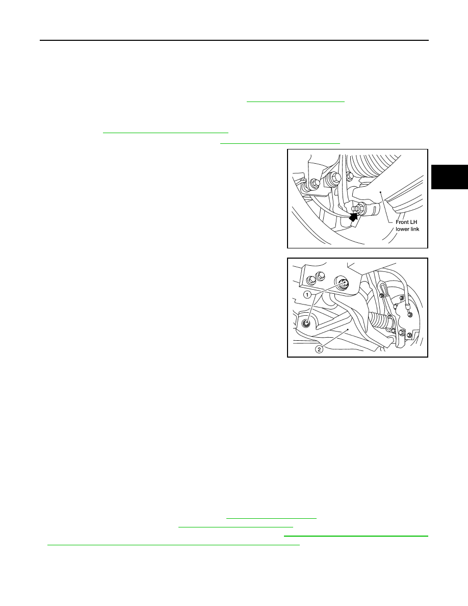
5. Remove the pinch bolt and nut from the steering knuckle using

power tool. Separate the lower link ball joint from the steering

knuckle.

6. Remove the lower link bolts/cam bolts (if equipped) (1) and nuts.

Remove the lower link (2).

INSPECTION AFTER REMOVAL

Lower Link

Check for deformation and cracks. Replace if necessary.

Lower Link Bushing

Check for distortion and damage. Replace if necessary.

INSTALLATION

Installation is in the reverse order of removal.

CAUTION:

• Do not reuse the upper link ball joint cotter pin.

• Do not reuse the lower link ball joint nut.

• Do not reuse the lower link nuts.

NOTE:

Some vehicles may be equipped with straight (non-adjustable) lower link bolts and washers. In order to adjust

camber and caster on these vehicles, replace the lower link bolts and washers with cam (adjustable) bolts and

washers.

• Tighten all nuts and bolts to specification. Refer to 

FSU-10, "Exploded View"

.

• Check the wheel alignment. Refer to 

FSU-5, "Front Wheel Alignment"

.

• Adjust the neutral position of the steering angle sensor. Refer to 

BRC-8, "ADJUSTMENT OF STEERING

ANGLE SENSOR NEUTRAL POSITION : Special Repair Requirement"

.

Inspection

INFOID:0000000009885605

• Check ball joint for grease leakage. Check dust cover for damage.

LEIA0097E

WEIA0153E

FSU-16

< REMOVAL AND INSTALLATION >

LOWER LINK

• Check the ball joint for excessive play. Replace the upper or lower link assembly if any of the following

exists:

- Ball joint stud is worn.

- Ball joint is hard to swing.

- Ball joint play in axial directions or end play is excessive.

NOTE:

Before checking the axial forces and end play, turn the lower ball joint at least 10 revolutions so that the ball

joint is properly broken in.

Measure the ball joint swinging force, turning force, and vertical end

play using a suitable tool.

• Measure at the cotter pin hole for upper ball joint as shown.

• Measure at the groove for lower ball joint as shown.

WEIA0076E

Swinging force (A)

Upper ball joint

: Refer to 

FSU-23, "Ball 

Joint"

.

Lower ball joint

: Refer to 

FSU-23, "Ball 

Joint"

.

Turning torque (B)

Refer to 

FSU-23, "Ball 

Joint"

.

Vertical end play (C)

Refer to 

FSU-23, "Ball 

Joint"

.

SFA858A

UPPER BALL JOINT AND LOWER BALL JOINT

FSU-17

< REMOVAL AND INSTALLATION >

C

D

F

G

H

I

J

K

L

M

A

B

FSU

N

O

P

UPPER BALL JOINT AND LOWER BALL JOINT

Removal and Installation

INFOID:0000000009885606

The ball joints are part of the upper and lower links. Refer to 

FSU-13, "Removal and Installation"

 (upper link),

FSU-15, "Removal and Installation"

 (lower link). 

FSU-18

< REMOVAL AND INSTALLATION >

KNUCKLE

KNUCKLE

Removal and Installation

INFOID:0000000009885607

REMOVAL

1. Remove the wheel and tire using power tool. Refer to 

WT-48, "Balancing Wheels"

.

2. Disconnect wheel sensor harness connector. Do not remove the wheel sensor from the wheel hub and

bearing assembly for this procedure.

3. Remove the wheel hub and bearing assembly. Refer to 

FAX-6, "Removal and Installation"

.

4. Remove the steering outer socket from the steering knuckle

using Tool. 

CAUTION:

• Be careful to not damage the ball joint boot.

• Temporarily tighten the nut to prevent damage to the

threads and to prevent Tool from coming off.

5. Remove the cotter pin and the nut from the upper link ball joint and discard the cotter pin.
6. Separate the upper link ball joint from the steering knuckle using

Tool.

7. Remove the stabilizer bar connecting rod lower nut using power tool. Separate the connecting rod from

the lower link. Refer to 

FSU-12, "Removal and Installation"

.

1.

Disc rotor

2.

Wheel hub and bearing assembly

3.

Wheel stud

4.

Splash guard

5.

Steering knuckle

Front

AWDIA0423GB

Tool number

: HT72520000 (J-25730-A)

WGIA0130E

Tool number

: ST29020001 (J-24319-01)

LEIA0095E


Content   ..  352  353  354  355   ..