Nissan Titan. Manual - part 352
ON-VEHICLE SERVICE
FSU-7
< PERIODIC MAINTENANCE >
C
D
F
G
H
I
J
K
L
M
A
B
FSU
N
O
P
• Always perform the following procedure on a flat surface.
• Make sure that no person is in front of the vehicle before pushing it.
1. Bounce the front of vehicle up and down to stabilize the vehicle height (posture).
2. Push the vehicle straight ahead about 5 m (16 ft).
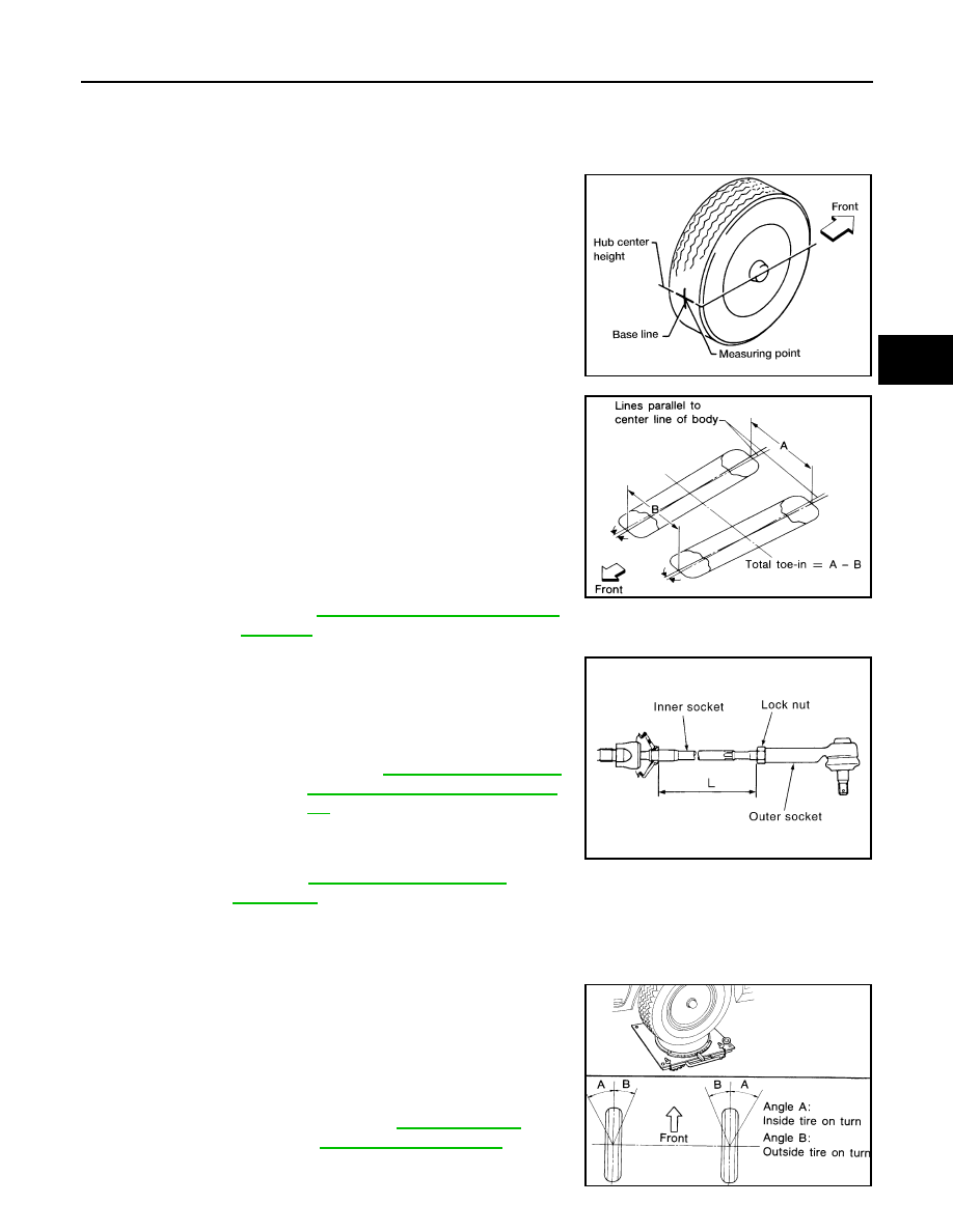
3. Put a mark on base line of the tread (rear side) of both front tires
at the same height as hub center as shown. These marks are
measuring points.
4. Measure the distance (A) on the rear side of the front tires as
shown.
5. Push the vehicle slowly ahead to rotate the wheels 180
°
degrees (1/2 a turn).
CAUTION:
If the wheels have rotated more than 180
° (1/2 turn), start
this procedure again from the beginning. Never push the
vehicle backward.
6. Measure the distance (B) on the front side of the front tires at the
same marks as shown. Total toe-in is calculated as (A – B).
7. Adjust the toe-in by varying the length of the steering outer
socket.
a. Loosen the outer tie-rod lock nuts.
b. Adjust the toe-in by screwing the outer tie-rods in or out.
c. Tighten the outer tie-rod lock nuts to specification.
FRONT WHEEL TURNING ANGLE
NOTE:
Check front wheel turning angle after the toe-in inspection.
1. Place front wheels on turning radius gauges in straight ahead
position and rear wheels on stands so that vehicle can be level.
Check the maximum inner and outer wheel turning angles for LH
and RH road wheels.
2. Start engine and run at idle, turn steering wheel all the way right
and left, measure the turning angle.
AFA050
Total toe-in : Refer to
SFA234AC
Standard length (L)
: Refer to
Socket and Steering Inner Sock-
et"
Lock nut
: Refer to
SGIA0167E
Wheel turning angle
(full turn)
: Refer to
.
SFA439BA